The VXWORKS7 real-time operating system
1) History
VxWorks is a multitasking real-time
operating system, typically
used in embedded systems.
This proprietary operating system, developed by Wind River (acquired by Intel in 2009), has been used by NASA for space
missions
VxWorks will be equipped
with innovative features that will bring it closer to market standards, in
particular thanks to its compatibility with the POSIX standard, python, containerisation. It is mainly used by research and industry (aeronautics, automobile,
transport, telecommunications, military)
2) Presentation
Vxworks is based on a
microkernel of a few Kbytes in size that manages a group of system processes.
This small kernel gives it the functionality and performance of a real time
executable. The Microkernel has four fundamental functions:
Message passing or IPC (interprocess
communication): The Microkernel handles messages from processes throughout the
system.
Task management or scheduler: the microkernel
works in close collaboration with the task manager. It is responsible for
allocating system resources to the tasks that require them. It is this part
that we will deal with later. The microkernel is executed following a system call
from either another process or a hardware interrupt.
Interrupts: All hardware interrupts are first
submitted to the kernel and then passed to the appropriate driver or system.
Low-level network communication, the kernel
delivers all messages to remote processes connected to the network.
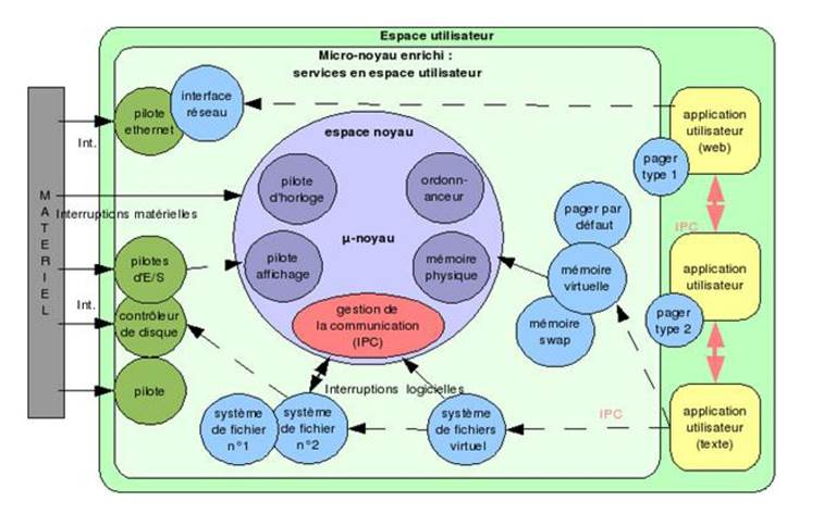
Addressing is virtual but no memory
protection in kernel space. There is a kernel address space for DKM kernel user
tasks and a user space for real time processes (RTP) in the system.
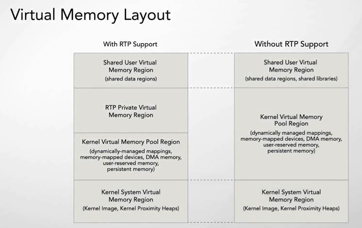
A
single address space at the kernel level implies :
ü Possible corruption of the executive's data by
applications - everyone sees everything. No memory protection.
ü Consistency of shared data between tasks therefore
requires synchronisation tools. Hence the following
abstractions of the executive :
·
Tasks.
·
Semaphores.
·
Message queue and pipes.
Why
a single kernel address space :
ü Smaller task context.
ü
No system call: services are invoked
by a simple function call.
ü
All application tasks are
"supervisor/privileged" tasks.
ü
Communication between tasks without
going through the operating system.
=
time saving
=
saving memory "space", resources
=
gain in predictability (see real-time embedded systems constraints).
Tips for
dealing with the demands of real-time multitasking
-
Deterministic behaviour
- A late
response is a bad response
- A
hasty answer may be the wrong answer
- Designed
for high speed - Fast response - Low overload
-
Correctly written code
- Only
uses CPU time when needed
Delays
or suspends when there is no work to do
- No
continuous scanning or endless waiting
3)
The Raspberry PI4 embedded hardware platform
3.1) Architecture
In practical work, we will use the :
Ø RAspberry PI 4
for vxworks
The Raspberry PI 4 is a low-cost stand-alone CPU board
for non-industrial embedded systems. It is part of a set of nano-computers that
have evolved over the years.
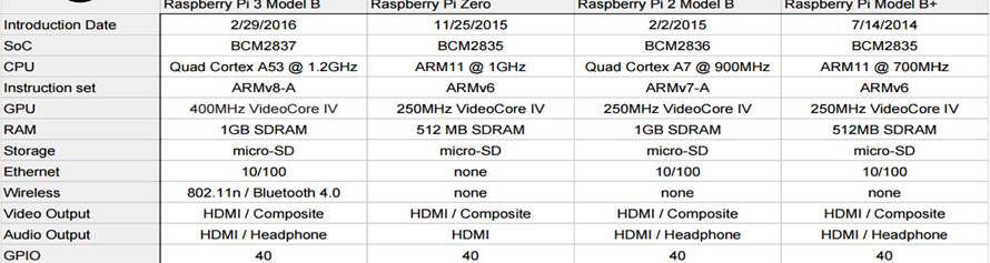
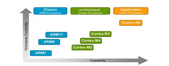
The processor used in the PI4 is compatible with ARM
cortex A-7 A-8 processors (application processors). ARM offers a wide range of
microprocessors for a variety of applications.
|
|
|||
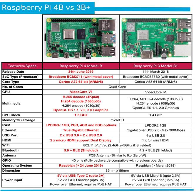
The BCM2711
processor on the Raspberry PI 4 board is part of the System on Chip (SOC) family
and is based on a low power ARM architecture:
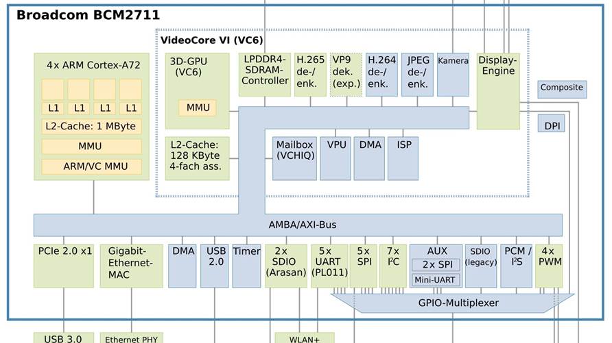
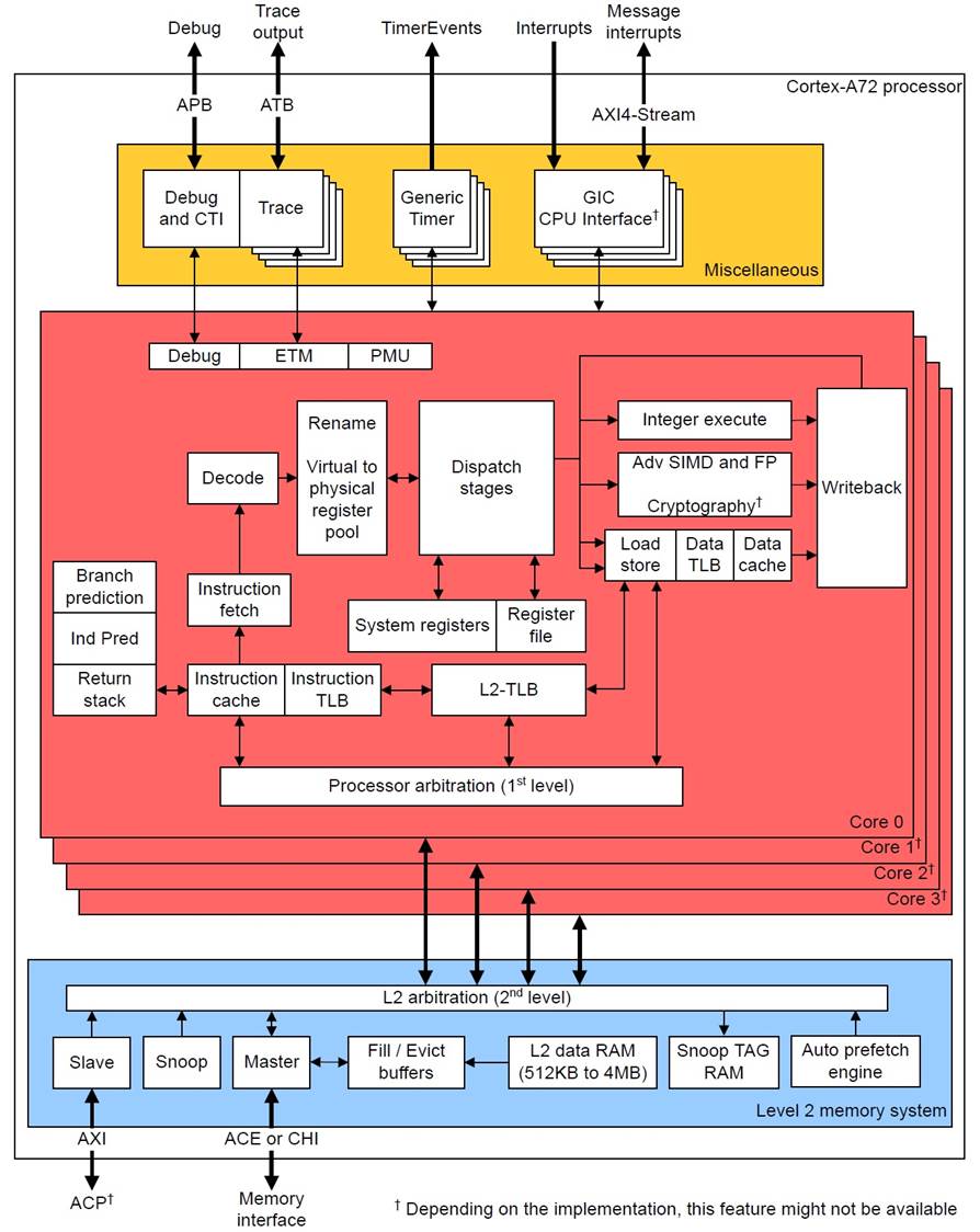
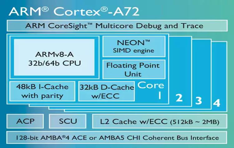
The SOC BCM2711 is
equipped with four ARM CORTEX A72 processors, with floating point computing
units.

All these elements are integrated on the same chip and are suitable for
a multitude of applications including HD video processing. These applications
can be :
Ø Navigation systems
Ø Multimedia player
Ø Medical monitoring systems
Ø Industrial vision
Ø Portable communication
Ø Graphics tablet
Its
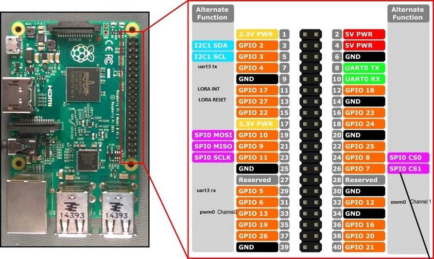
40-pin expansion connector has the following format:
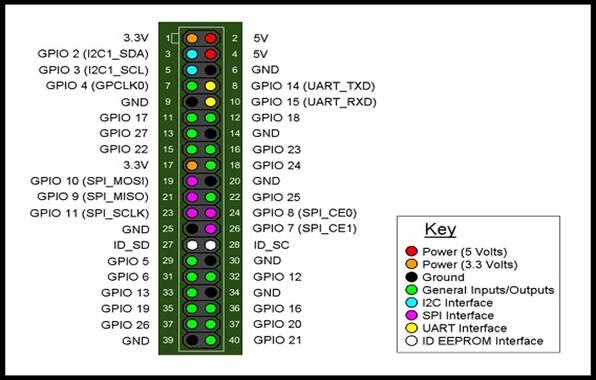
This card can host an embedded Linux type operating system Xenomai Android ...
3.2) Access to the operating
system
Like many embedded environments (ECU), the card can be
remotely controlled by pre-installed network services:
Ø In TELNET client and server console
mode
Ø Using the
console port on an RS232 V24 serial link
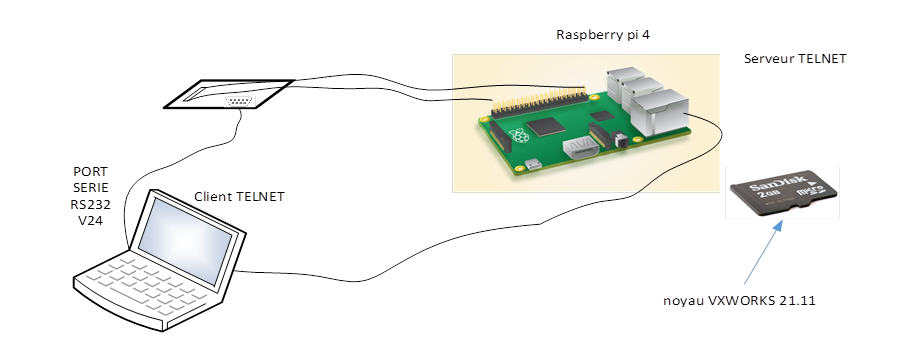
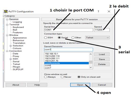
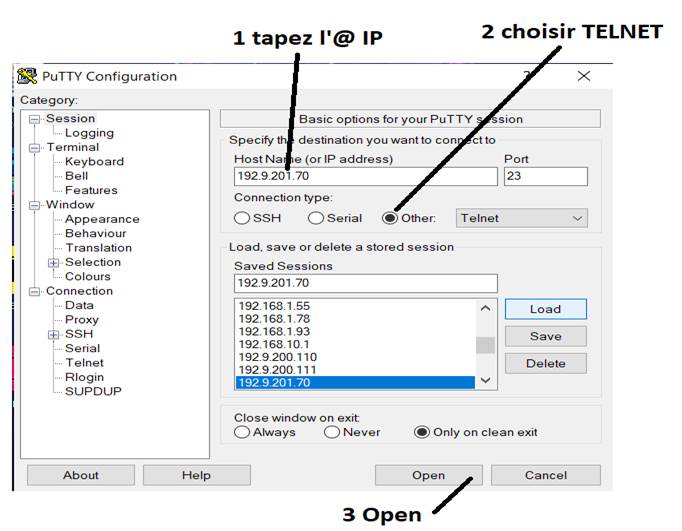
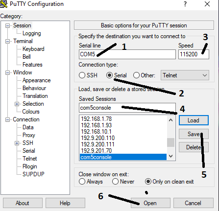
Open Putty on the windows environment:
|
|

Configure putty with the RS232 serial link
configuration
The boot loader and the Vxworks
kernel launch:
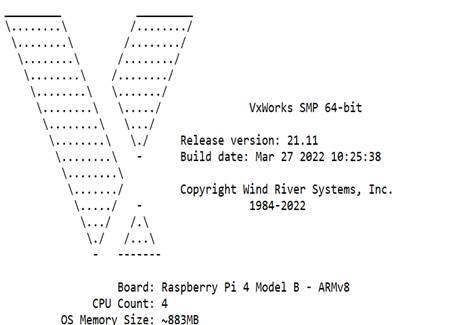
The code interpreter is waiting. It is waiting for
code written in C
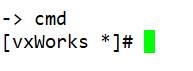
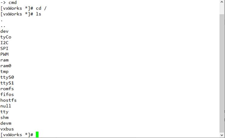
To switch to the command interpreter type cmd
To know our network configuration in order to use the
TELNET service type the following command:
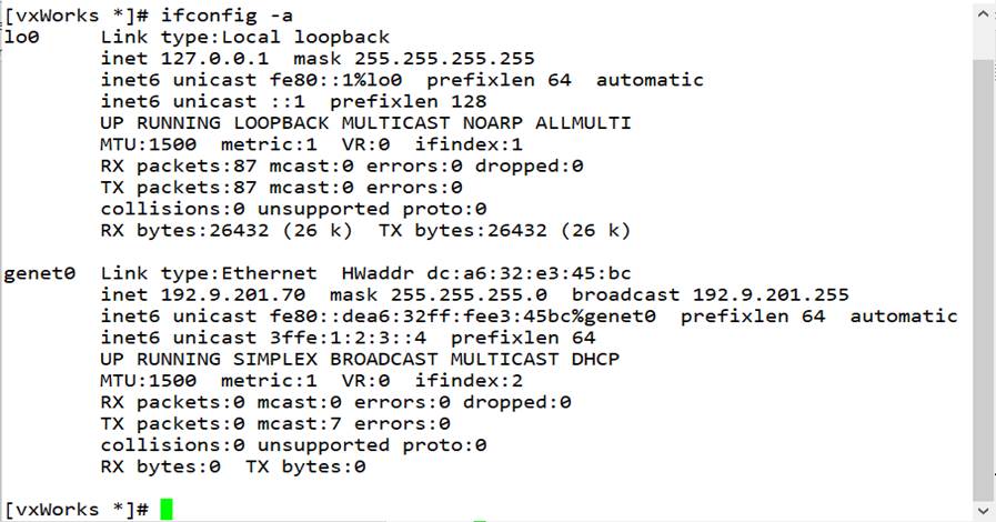
Our IP address appears in the box. This is static and
hard coded when the Vxworks kernel was built. The
file system used is FAT and we can see the directories of the kernel root :
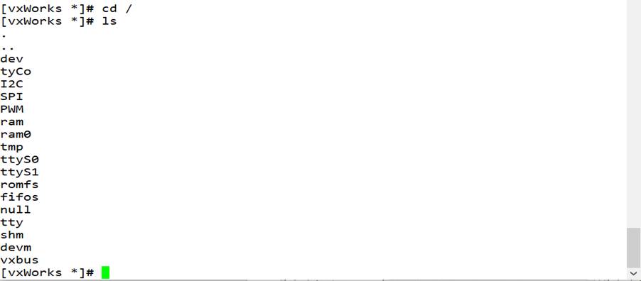
To return to the code interpreter type C

We will then connect with the TELNET network service
The code interpreter is waiting. It is waiting for
code written in C
In terms of programming VxWorks has two types of
tasks:
ü Kernel
spots or DKM (downloadable module kernel)
ü Main or
thread tasks encapsulated in a real time process (RTP real time process)
In the rest of this handout, we will discuss these different software
elements
Real-time tasks in vxworks kernel space
4) Présentation
They are
created as DKMs (downloadable kernel modules)
task = code execution unit
A thread of execution: the PC Processor registers
One entry point, one status, one priority
-The task is not the code
Two distinct tasks can be associated with the same code segment (but different data and stack segments)
· All tasks share the same address
space as the kernel
Tasks are managed by their ID (TID)
-
Each task has its own saving context in the TCB (Task Control Block)
A
DKM task in memory can be represented as follows:
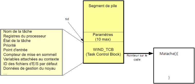
The use of kernel
space gives direct access to functionality and I/O for maximum speed;
To switch a new task to execution, the kernel must :
-
Save the context of the running task in its TCB structure.
- Restore the context of the new task to be executed
from its TCB structure.
The TCB (Task Control Block) structure is
defined by the WIND_TCB data structure in the taskLib.h
file. It contains information about the CPU context, pc, sp, cpu registers, fpu registers as well as about the task, priority, flags,
etc...
The kernel manages a particular queue for each of the
possible task states.
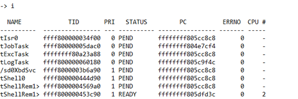
To create a core spot
int taskSpawn
(
char * name, /*
name of new task (stored at pStackBase) */
int priority, /*
priority of new task */
int options, /*
task option word */
int stackSize, /* size (bytes) of stack needed plus name */
FUNCPTR entryPt, // address
of code to execute
int arg1, /* 1st of
10 req'd task args to pass
to func */
int arg2,
int arg3,
int arg4,
int arg5,
int arg6,
int arg7,
int arg8,
int arg9,
int arg10
)
Setting up a kernel task with the
workbench tool
In workbench, create a project for a DKM kernel module
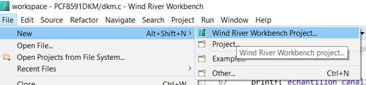
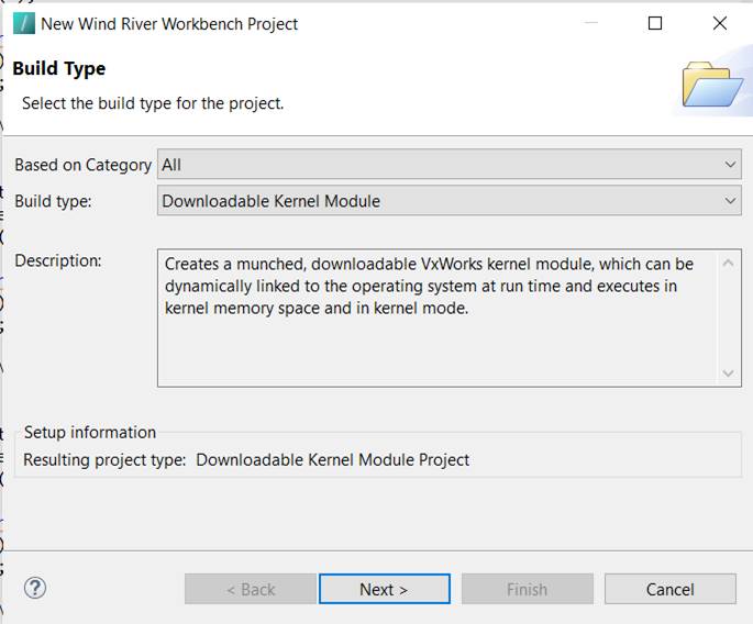
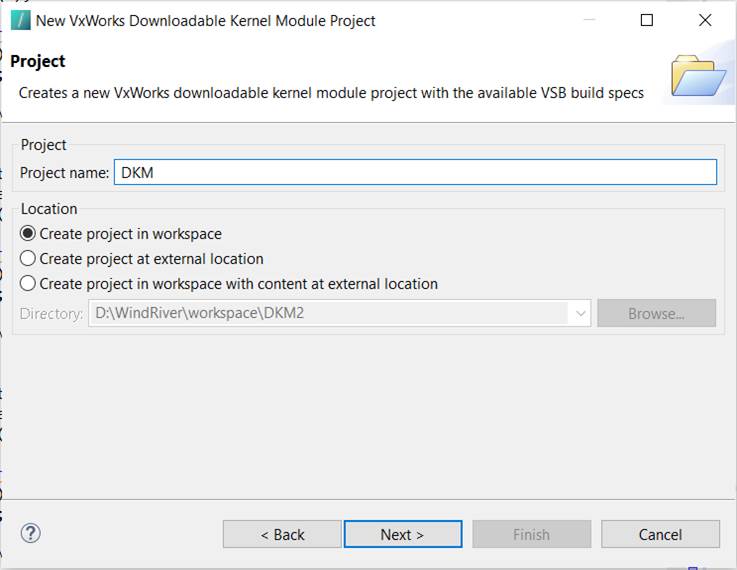
Complete the following source code
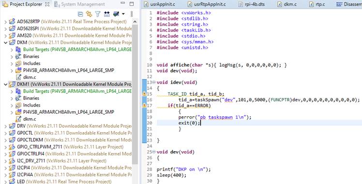
@ What is
the size of the battery?
@ What is
the priority of the task?
@ What is
the name of the function associated with this task?
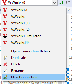
Click on the connection window at the top of the page,
Select new connection
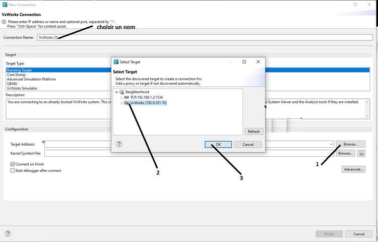
Choose the following 4 steps
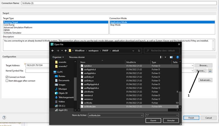
Indicate where the vxworks.bin
kernel image is located in PI4VIP
Click on finish
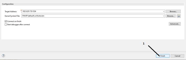
The connection was successful

Right click on your project and then run debug kernel
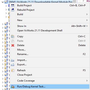
Select our module
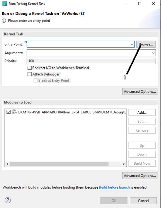
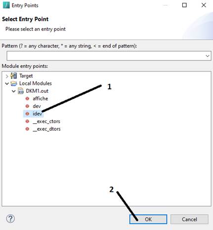
Select the name of the main task
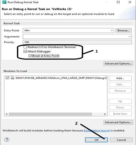
Follow the two steps
Connect to the
serial port, the console port with the putty utility
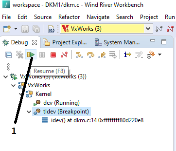
Start our task

We will move to the image of the module present on the
PC

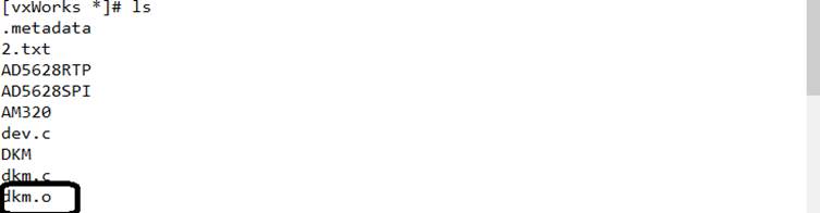
To
launch the module load it

Return to the code interpreter
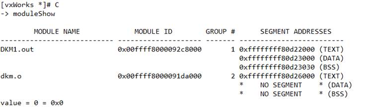
Then launch the
task associated with this module

Compiling
and executing a kernel module via a cross-compiler.
Launch the xubuntu virtual machine and open a LINUX console
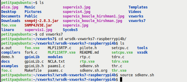
Run the compilation
of our kernel module and copy it to a directory dedicated to FTP transfer

Create a network
link to the FTP server on PI4 using the IP address of the xubuntu
VM
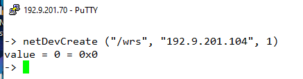
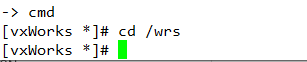
Go to the wrs directory in the root of the PI4 with the command
interpreter
Load the module

Run the function
associated with the kernel module task

Real-time
RTP processes
5.1) Presentation
An RTP
is just a container of tasks. RTP tasks are added together in a task queue in
the same way as DKMs
A real-time process has its own memory space within the user space
The RTP instance is created from a . vxe file
Memory protection and separation is enforced by the MMU - the MMU creates
a virtual memory space for each RTP
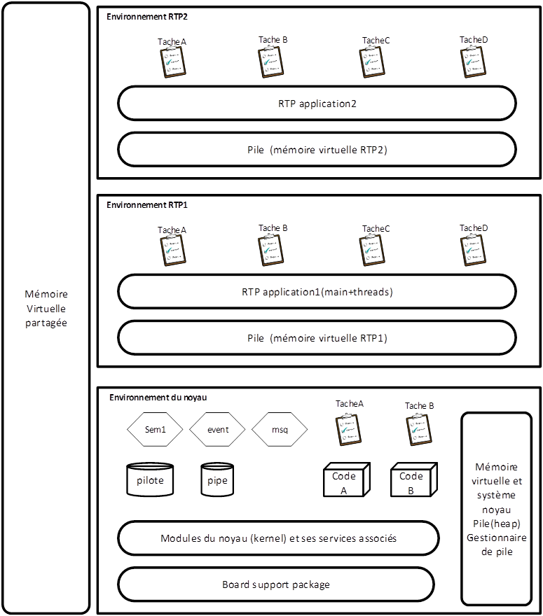
Each process has its own address space and
is protected from other processes
Kernel space is protected
from processes in user space
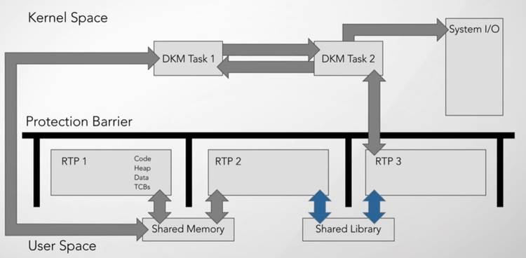
Real-time
processes are dependent on events external to the computer. As these events are
not under the control of' , several tasks can compete for the'
processor allocation. The exchange of data between the kernel space and the RTP
space is done through a shared memory
RTP_ID rtpSpawn(
rtpFilename, //
Path to the vxE executable
argv,
//Argument list to be passed to main
envy,
//Environment
variable
list
priority,
// Task priority for the initial task
uStackSze,//
Maximum stack size for the initial task
options, Options for the
RTP
taskOptions //
Options for the initial task
)
RTP_ID return value
is ok for success or NULL for error
The vxworks shell can be
used to start an RTP process:
/home/myvxapp.vxe first second third
or rtp exec /home/myvxapp.vxe first
second third
For the C code
interpreter
rtpSp " myvxapp.vxe first second third "
ou rtpSpawn(“myvxapp.vxe”,
----------------------------------)
The use of
processes can partition the system for greater reliability
- The use of the
protected memory model means that areas where speed is essential can use kernel
space, while other code can use process space for safety
Normal
operation of VxWorksscheduled tasks, not RTPs
- An RTP must have
at least one task to continue to exist
- The task in an
RTP has a priority value, just like a kernel task, and is placed in the same
ready queue
- A task in user
space has a part of its task control block in kernel space that the scheduler
can use, and this part is not accessible by the RTP
- RTP user space
exceptions are handled by the kernel
Benefits for the
RTP project
- A system using
RTP projects is more resistant to software defects.
The protection of
RTP memory is not at the expense of real-time determinism.
- It is easier to
port LINUX software to VxWorks RTP projects than to VxWorks Downloadable Kernel
Module (DKM) projects
Disadvantages of
the RTP project
- RTP process
kernel API calls in user mode have higher latency.
- The user-mode RIP
kernel API is a subset of the kernel application API.
- Using RTP
projects increases the memory footprint of the VxWorks kernel and system
The initial task in
RTP starts at main() and must stay alive
- Tasks
in a PTR
- Sharing code and
data within the RTP
- Can generate more
tasks in the RTP
- Unable to access
code or data outside the RTP
- Uses system calls
to access kernel features such as semaphores
- Can communicate
with other RTPs and kernel tasks using shared public object data
An RTP process does
not have direct access to the kernel space file descriptor
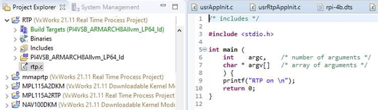
Create a new
project of type RTP and complete your source file as follows:
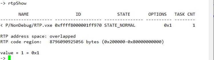
How to get the list
of processes in memory under vxworks
rtpShow() ;
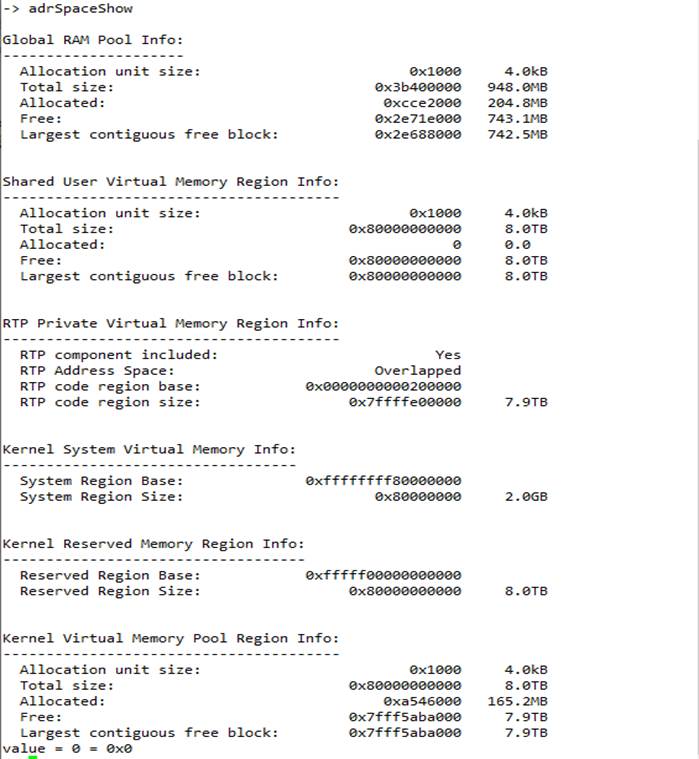
View the memory
space managed by vxworks
adrSpaceShow
|
|

View the list of device descriptors maintained by the vxworks kernel
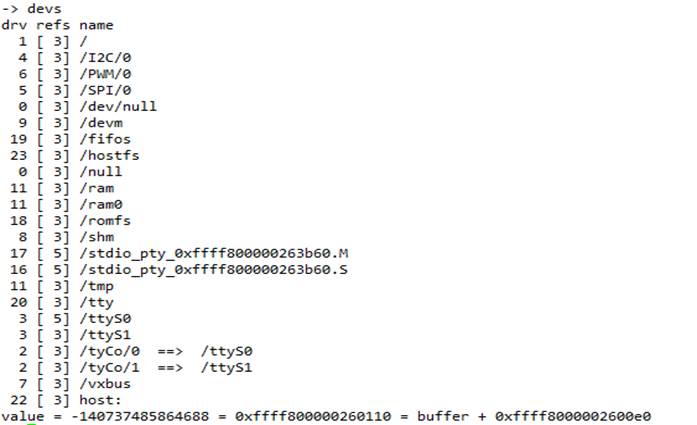
@ the
console port is managed by a serial RS232 /ttyS0 device, what is its driver
number?
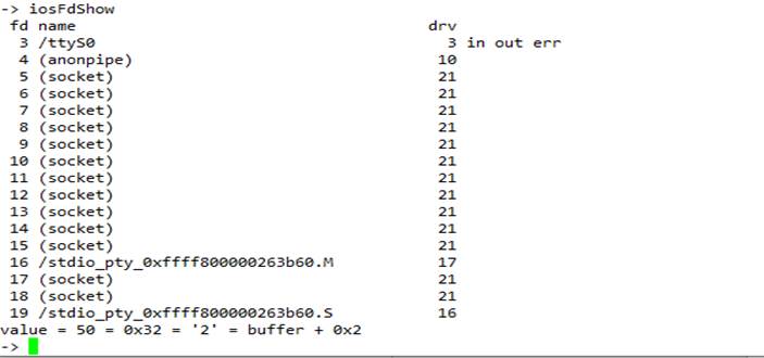
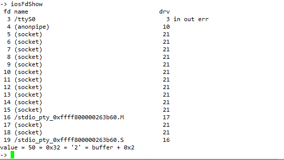
View the list of file
descriptors managed by the vxworks kernel
The various DKM or
RTP (main + thread) tasks are scheduled in a multi-tasking SMP (symmetric
multiple processor) context with 4 cores of the CORTEX A72 type. These tasks
are distributed to the four cores thanks to two scheduling techniques that we
will present below.
6.1) Operation of
the scheduler.
The scheduler is the heart of the real-time
kernel. It is invoked at each task switching as well as' at each
call to a system function (semaphore, signal, queue, ... )
Scheduling
occurs if :
-
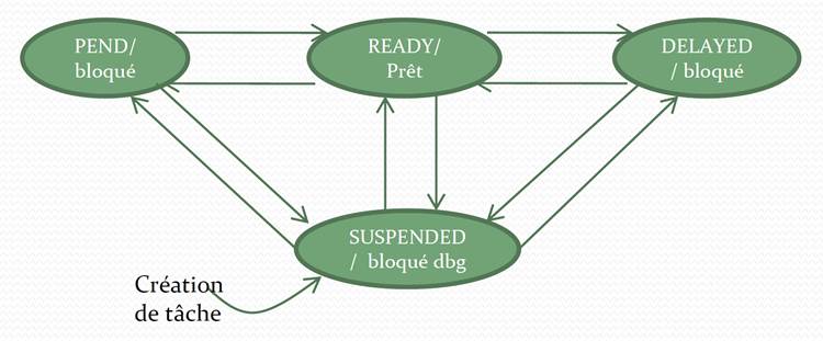
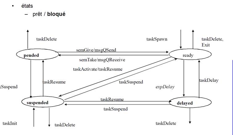
The running task is set to pending, delayed or suspended.
-
A higher priority task goes into the ready state (pre-emption).
- Time-slice elapses if at least one other task with
the same priority is ready.
The
priorities.
The priority of a
task is encoded in one byte:
-
0 = highest priority
-
255 = minimum priority
- 100 = default priority
VxWorks does not implement dynamic priority
management. If a task A is never blocked or delayed, then a lower priority task
B will never be executed.
If several tasks have the same priority, it is then possible to run the scheduler in "round robin" mode between them. (priority scheduling with multiple queues).
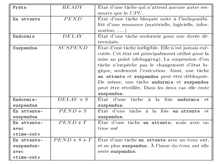
6.2) Task
scheduling techniques
We have
seen that the system executes the ready task with the highest priority.
Scheduling
occurs when several tasks with the same priority are in the ready state.
Vxworks offers
two different methods for the election of tasks, called scheduling:
ü FIFO scheduling
ü Round Robin scheduling
All real-time
processes or tasks in the system use one of these two methods, but two
different tasks or processes may use a different method.
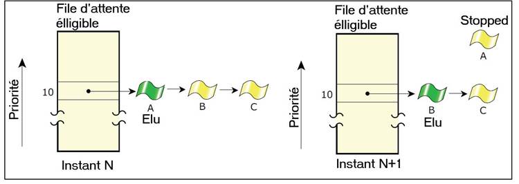
a) FIFO
(First In First Out) scheduling
In the case of FIFO scheduling, a task runs until it :
ü frees up the processor (it terminates or makes a
system call, for example)
ü is pre-empted by a
higher priority process
b) Round Robin Scheduling
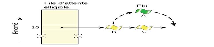
In the round-robin principle,
a task runs until it is completed:
ü voluntarily gives up processor
resources
ü be
preempted by a higher priority
ü uses all
its timeslice (processor allocation time) under the
control of the scheduler
c) The changing context
-An interruption (e.g. from an external device or
timer) will cause a context switch
- Context switching is synchronous if it is controlled
by the task, e.g. a wait or delay, or a higher
priority task being ready to run
- Context switching is asynchronous if it is caused by
an interrupt, such as a timer
To activate time slicing.
Where ticks are the number of system times per slice
STATUS kernelTimeSlice
(
int
ticks /* time-slice in ticks or 0 to disable round-robin */
)
This routine allows a round robin selection among
tasks of the same priority and defines the system time slice (ticks) assigned.
The round robin is disabled by default. A time slot of zero ticks disables
round robin.
- To disable time slicing :
kernelTimeSlice(0)
- To find the system clock frequency :
_Vx_freq_t sysClkRateGet(void)
Returns the number of ticks per second of the system
clock.
- To find the
period of a time slot in ticks :
STATUS kernelTimeSliceGet
(
ULONG *
pTimeSlice /* current time-slice in ticks */
)
This routine returns the time slot in ticks for the
system.
- In cooperative
multitasking to give up the CPU temporarily, the programmer calls
STATUS taskDelay
(
Vx_ticks_t ticks /* number of ticks to delay task */
)
This routine causes the calling task to abandon the
CPU for the specified time in ticks.
The state of the task is changed to delayed (not
ready) until the specified number of interrupts
has occurred. For example, a taskDelay(
) with a tick value of 1 will wait until
the next interruption of the system clock; in this
case, the time the task is delayed is less than a tick period. Once the delay
expires, the state of the task reverts to ready (unless it was suspended or
stopped during the delay) and becomes eligible to be scheduled for execution.
Calling taskDelay() with a
tick value of 0 forces the scheduler to shuffle the ready queue, allowing tasks
of the same priority as the calling task to have a chance to run. If there is
no task of the same priority as the calling task in the ready queue, the
calling task will resume execution immediately.
The list of tasks :
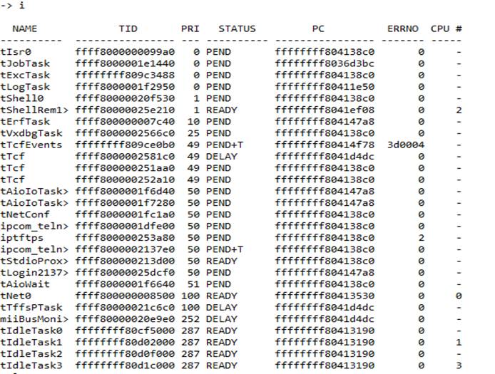
Tisr0: task that executes for an ISR
interrupt service routine
tjobtask: task
that executes fcts for other tasks
tlogtask: task
that runs fcts for log messages
tshell0: task that runs the shell displays
data on the screen
terftask: the
new storage drivers use this task to interface between the system and vxworks
tvxdbgtask: used
by debug routines (breakpoint)
task: tcf tcfevent for the agent
Tnetzero: task
that allows direct access to the network stack and network drivers
Tai0: to manage the queue for I/O read and
write requests
Tnetconf:
listens for interfaces that try to connect to the network stack and configure
them
the troot task
: allows to make the first tests when it boots after troot
the system is in SMP
Kill the tNet0 spot
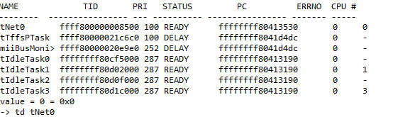
@ What do
you notice?
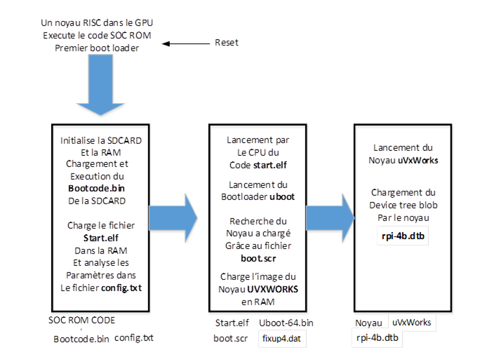
vxworks7 boot sequence on the
Raspberry PI4 platform
Before the Vxworks kernel
launches, several bootloaders specific to the Raspberry PI4 and the ARM
processor are required:
|
Name |
Role |
Format |
|
Bootcode.bin |
Bootloader replaced by EEPROM on PI4 |
Binary |
|
Start.elf |
ARM code executed by the CPU |
Binary |
|
Fixup4.dat |
Configures the GPU/CPU SDRAM |
Binary |
|
Config.txt |
Configuration parameter for u-boot |
text |
|
rpi-4b.dtb |
Device tree blob |
text |
|
uVxWorks |
Core |
Binary |
|
Boot.scr |
Command line to load and run the kernel |
text |
|
u-boot-64.bin |
bootloader |
binary |
Although the overall start-up process of VxWorks 7 is
similar to previous versions, the details have changed considerably. The main
differences are:
VxWorks itself no longer includes ROMable
code to run directly from the reset and boot the system.
VxWorks 7 uses a
Linux-style device tree to define the hardware;
The device tree must usually be loaded into memory as
a binary DTB (device tree blob) before the VxWorks kernel is started.
Instead, the hardware must have an independent boot
loader installed to run from the reset and boot the system.
If you are using a commercial off-the-shelf hardware
design, the boot loader will probably be U-Boot. For example, it can boot other
operating systems such as Linux.
When the Raspberry Pi 4 Model B powers up, the ARM
processor is offline and the GPU will boot the SOC with the GPU specific
firmware (SOC EEPROM which has replaced the Bootcode.bin file located in the SD
card boot partition).
The start4.elf and
fixup4.dat files
start4.elf is the Pi4 GPU firmware. Fixup_file (fixup4.dat) Specifies the memory location in
the start_file(start4.elf ) to match the GPU memory
split file. Note that start_file and fixup_file are corresponding and closely related file
pairs.
start4.elf is also
responsible for loading and modifying dtB files
(memory size, Ethernet address...). ), which performs simple customisation functions.
This boot loader will in turn boot the ARM image
executable. U-boot is used as the initial ARM executable image to boot the ARM
code.
The DTB stores the boot line passed to the VxWorks
kernel. Specifically, the boot line is written to the selected node of the
device tree. The VxWorks kernel extracts this information from the device tree
and parses it as necessary.
bootargs =
"usb2End(0,0)host:vxWorks h=192.9.201.7
e=192.9.201.70:ffffff00 g=192.9.201.8 u=target pw=vxTarget
o=genet0 f=0x40";
stdout-path = "serial1";
U-Boot can boot two types of VxWorks images: uVxWorks and the raw bin file vxWorks.bin.
The uVxWorks is used with the U-Boot "bootm" command and requires an independent DTB file.
The vxWorks.bin is used with the U-Boot
"go" command and requires a DTB embedded in the kernel.
The boot.scr file
will allow uboot to load and run the kernel
It contains the
following commands to load and run a VxWorks Kernel on an ARM card from an SD
card.
fatload mmc 0:1 0x10000000
uVxWorks
bootm 0x10000000
The VxWorks entry point is _sysInit(
) in sysALib.s. This assembly routine sets the
initial hardware state and then jumps to usrInit( )
in usrConfig.c.
usrInit( ) is the first C
routine executed from a VxWorks image.
This routine initializes the cache, initializes the
vector table, performs a card-specific initialization, and then starts the
multitasking kernel with a user-boot task.
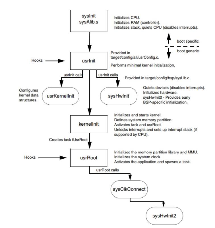
The purpose of the usrInit(
) routine is to completely initialize the CPU and shut down all other hardware,
thus preparing the way for the kernel to initialize and boot itself. This
routine is found in prjConfig.c but calls routines in
several other files, some of which must be supplied by you and some of which
are supplied by Wind River. Normally,
it is not necessary to modify the usrInit(
) routine provided by Wind River. However, the sysHwInit(
) routine that must be called from usrInit( ) usually
requires modification. The sysHwInit( ) routine
ensures that the board-dependent hardware is idle. sysHwInit(
) is provided in the BSP or reference template and is found in sysLib.c.
The usrInit( ) routine (in prjConfig.c) records the boot type information, handles all
the initializations that need to be done before the kernel actually boots, and
then starts the kernel execution. This is the first C code to run in VxWorks.
This routine is called in supervisor mode with all
hardware interrupts locked.
Many features cannot be called from this routine.
There is no task context yet - that is, no task control block (TCB) and no
thread stack - so features that require a task context cannot be called. This
includes any functionality that may cause caller preemption (such as
semaphores) or any functionality that itself uses such functionality, such as printf(). Instead, the usrInit( )
routine
does only what is necessary to create the initial
thread, usrRoot( ). The initialization operations
performed in usrInit( ) include the following:
■ Cache initialization.
The code at the beginning of usrInit()
initializes the caches, sets the mode of the caches and places the caches in a
safe state. At the end of usrInit(), the instruction
and data caches are enabled by default.
■ Reset
the BSS segment of the system.
The C language specifies that all uninitialised
variables (stored in bss) must have initial values of
0.
As usrInit( ) is the first C
code to run, it clears the section of memory containing bss.
■ Initialization
of interrupt vectors.
Exception vectors must be initialized before enabling
interrupts and starting the kernel.
First, intVecBaseSet()
is called to set the base address of the vector table.
After calling intVecBaseSet(
), the excVecInit( ) routine initializes all
exception vectors
to default handlers. These handlers safely intercept
and report exceptions caused by program errors or unexpected hardware
interruptions.
■ Initializing
the system hardware to an idle state.
Calling the sysHwInit( )
system routine initializes the system hardware. Initialization is mainly about
resetting and disabling hardware devices. Otherwise, when the kernel is booted
and interrupts are enabled, these devices may cause unexpected interrupts. In
VxWorks, ISRs (for I/O devices, system clocks, etc.) are not connected to their
interrupt vectors until system initialization is completed by the usrRoot( ) task. This is a requirement because the memory
pool is not yet initialized. You should not connect an interrupt handler to an
interrupt during the sysHwInit( ) call; this requires
memory allocation, which is not available at the moment. Most interrupt
connections occur later in the sysHwInit2( ) routine in sysLib.c.
■ Calling
kernelInit( ).
The VxWorks libraries contain the code for kernelInit(). Therefore, it is not normally available to
BSP developers in source form. The kernelInit( )
routine starts the multitasking environment and never returns.
The kernelInit( ) routine is
provided by Wind River in an archive file of the VxWorks library. The purpose
of this routine is to make the kernel operational so that any subsequent
initialization can be performed as a task running under the kernel.
The name of this task is tRootTask,
and the routine it executes is usually usrRoot().
The kernelInit( ) routine
calls intLockLevelSet( ), disables round-robin
scheduling and creates an interrupt stack (if supported by the architecture).
The routine then creates a root stack and a task control block (TCB)
from the top of the memory pool, generates the root
thread usrRoot() and terminates the execution thread usrInit(). At this point, the interrupts are enabled. It is
essential that all interrupt sources are disabled by usrInit()
and that all pending interrupts are cleared.
The purpose of the usrRoot(
) routine is to complete the initialization of the kernel and all hardware, and
then to run any application code.
This routine is provided by Wind River in the prjConfig.c file and the original copy should not be
modified.
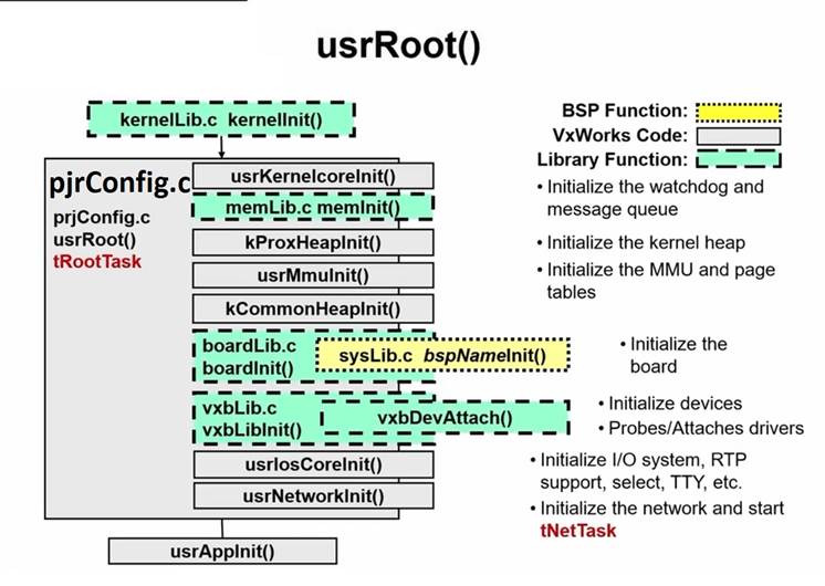
During development, prjConfig.c
is often temporarily copied to the BSP directory and debugging changes are made
to the temporary copy. prjConfig.c is also
configurable with macros defined in config.h. It
initializes the kernel services events, semaphores, messages ...
The usrRoot( ) routine calls
the memInit( ) routine to initialize memory.
Optionally, usrRoot( ) can call the memShowInit( )and usrMmuInit( )
routines. Once the system is multitasking, the BSP calls its first routine, sysClkConnect( ). sysClkConnect(
) immediately calls the sysHwInit2( ) routine. sysHwInit2( ) is responsible for
any map initialization not completed in sysHwInit( ),
such as connecting interrupt sources using intConnect(
). Then the usrRoot( ) routine continues the clock initialisation.
It sets the default clock rate to the value of
the SYS_CLK_RATE macro, usually 60 Hz. usrRoot( )
then enables the system clock with a call to sysClkEnable(
). Once the clock is initialized and running, several kernel modules, such as selectLib, the I/O subsystem and the console, are
initialized. It calls the initialization functions of the board support
package, the vxbus to probe the devices and attach
the drivers. It ends by calling the usrAppInit
function to initialise the applications.
8) The device tree
For several years now, support for the ARM
architecture in the kernel has been gradually shifting to the Device Tree for
hardware description.
Before the introduction of the Device
Tree, a very large amount of C code in these directories of the arch/arm/
kernel was used to describe all the peripherals of each SoC, and then all the
peripherals of each electronic card embedding an SoC.
Since the ARM architecture does not provide a dynamic enumeration mechanism
(USB PCI), it is necessary for the kernel to know in advance all the
peripherals of the system and their characteristics. The kernel must describe,
in the form of C code, all the peripherals of each SoC and each electronic
board, which becomes very cumbersome.
The move to the Device Tree was therefore part of this
great movement to clean up and refactor support for the ARM architecture in the
.
The basic principle of the Device Tree is to describe
the hardware of a system and to pass this hardware description to the operating
system when a platform is started.
With the Device Tree, each hardware platform is
described by a file called Device Tree Source (DTS or DTSI).
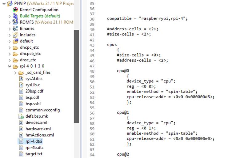
When the kernel is compiled, these DTS files are
transformed into a binary format called Device Tree Blob (DTB) using a special
compiler called Device Tree Compiler (DTC). This transformation is mainly used
to provide a more efficient format to parse than a text format.
Starting up with U-Boot
To boot a kernel using the Device Tree to describe a
hardware platform, the boot loader will need to load two :
the uVxworks kernel image
and the Device Tree Blob rpi-4.dtb .
Note that the boot loader is allowed to adapt the DTB
before passing it to the kernel, for example to pass information such as the
kernel command line or the MAC address of the different network interfaces.
As the name suggests, a Device Tree is a tree,
consisting of a set of nodes nested within each other. Each of these nodes can
contain a set of properties and sub-nodes. Here is an extract of a Device Tree,
from the file rpi-4.dtsi
uart0:
serial@fe201000
{
compatible = "brcm,bcm2711-pl011", "arm,pl011", "arm,primecell";
reg = <0x0 0xfe201000 0x0 0x0200>;
interrupts = <153 0 4>;
interrupt-parent = <&intc>;
clock-frequency = <48000000>;
pinmux-0 = <&uart0_pins>;
fifo-disabled = <1>;
status = "disabled";
};
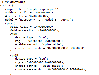
At boot time, the kernel receives in the registry the
address of the DTB and will therefore be able to browse it to discover the
hardware of the platform on which it is running. In particular, for each node
in the Device Tree that is a child of a node identified as a single-bus, the
kernel will instantiate a platform_device structure
representing that device.
9) Device drivers
9.1) The VxBus
architecture
The driver architecture is based on VxBus (Vxworks bus). VxBus provides a consistent device driver model that is
both architecture and BSP independent
VxBus is
intended to provide device driver developers with the following functionality:
·
The possibility of organising devices in a
simple topology.
•
The ability to create drivers that can be loaded and unloaded on the
fly.
•
A mechanism for managing the device's resources (BARs, IRQs).
•
A mechanism for managing parent/child relationships.
•
Improved portability of the driver.
•
Independence of the BSP and architecture.
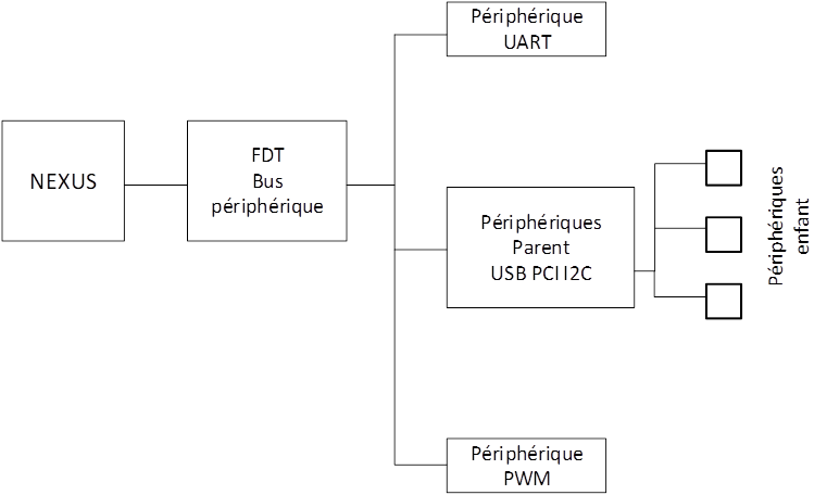
Vxbus uses the device tree to manage
devices in a simple topology:
9.2) C language description of a device
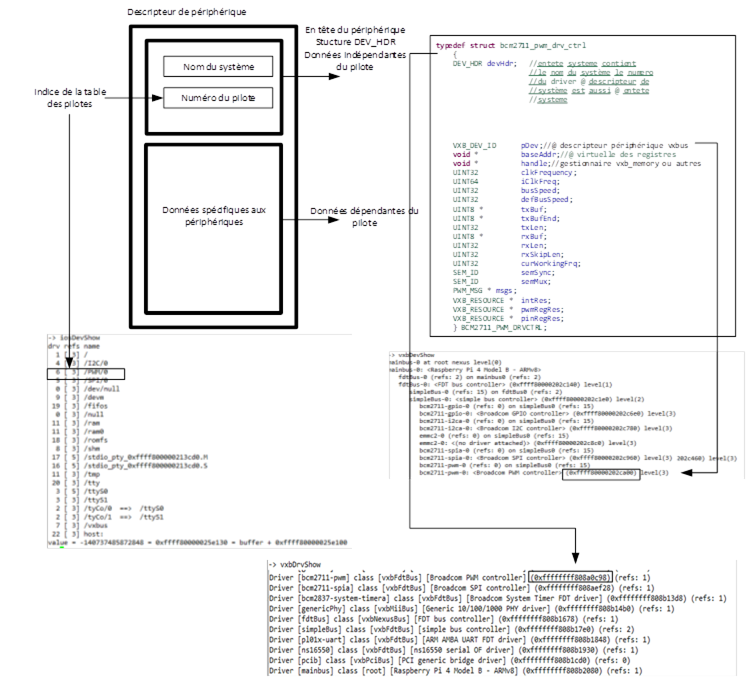
Device descriptors
Each device is
described by a structure with two parts:
ü An independent part of the device
DEV_HDR the name, number and @ of the system descriptor
ü
A part dependent on the device registers, interrupts, pins, frequency
...
The VXB_DRV driver
and driver management structure
Drivers in VxBus are defined
using a VXB_DRV structure that includes identification information and a method
table. This structure is used to manage drivers in the VxWorks system.
Initialization
of the structure
VXB_DRV
vxbFdtBcm2711GP0CtlDrv =
{
{ NULL } ,
"bcm2711-gpoctl",
/* Name */
"Broadcom GPO CLK controller", /* Description */
VXB_BUSID_FDT, /*
Class */
0,
/* Flags */
0,
/* Reference count */
bcm2711GP0CtlDeviceMethods
/* Method table */
} vxbSampleDrv;
LOCAL VXB_DRV_METHOD bcm2711GP0CtlDeviceMethods[] =
{
/* DEVICE API */
{ VXB_DEVMETHOD_CALL(vxbDevProbe),
vxbBcm2711GP0CtlProbe },
{ VXB_DEVMETHOD_CALL(vxbDevAttach),
vxbBcm2711GP0CtlAttach },
{ VXB_DEVMETHOD_CALL(vxbDevShutdown),
vxbBcm2711GP0CtlShutdown },
{ VXB_DEVMETHOD_CALL(vxbDevDetach),
vxbBcm2711GP0CtlDetach },
VXB_DEVMETHOD_END
};
An array of methods usually contains
the vxbDevProbe,
attach, stop and detach methods and their mapping to the source file methods.
The list ends with an empty entry. The vxbSampleDrv driver definition includes a pointer to this
table.
The macro
VXB_DRV_DEF( ) has a special function; it declares the driver structure as part
of a link set.
VXB_DRV_DEF(vxbFdtBcm2711GP0CtlDrv);
It is this set of
links that the kernel will use to call all the probe methods of the drivers and
compare the device name in the device tree with the one provided by the probe
method
A mapping table is used by the pilot's probe method to
make this comparison.

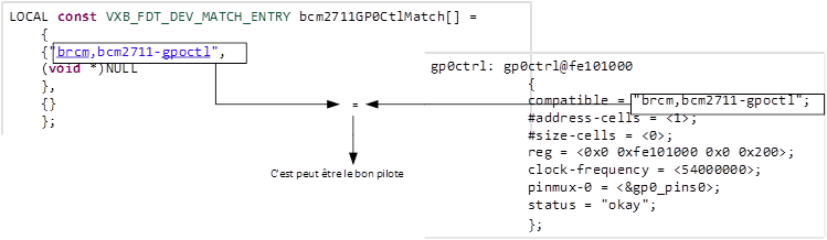
The vxbDevProbe( ) function
matches the device with an existing driver by calling the vxbFdtDevMatch(
) method or vxbPCIDevMatch( ) for PCI
LOCAL STATUS vxbBcm2711GP0CtlProbe
(
VXB_DEV_ID pDev
)
{
/*
* Probe logic really depends on the device.
*/
//SPI_DBG (SPI_DBG_INFO, "probing for device
match.\n");
return vxbFdtDevMatch (pDev, bcm2711GP0CtlMatch, NULL);
}
the vxbFdtDevMatch( )
function matches the DTB device with the driver.
An unattached pilot
gp0ctrl-0 (refs: 0) on simpleBus0 (refs: 15)
gp0ctrl-0: <(no driver attached)>
(0xffff80000202cb40) level(3)
The vxbDevAttach( ) method
allows the device to be attached to the driver by :
ü
Allocating memory resources for the driver
ü
Retrieve information from the device tree
ü Calls the device initialisation function
ü Handles
interruptions
ü
Calls ttyDevCreate() to create a device
terminal
9.3)
Managing memory resources
The objective of resource management is to provide a
standard resource structure to describe the different types of resources
(memories, inputs, outputs, interrupts) and to store them in an object
referenced by a pointer in the VXB_DEV structure.
VxBus GEN2 introduces the VXB_RESOURCE
abstraction concept to manage register banks and interrupts.
Each resource has a
common parent structure VXB_RESOURCE and a child VXB_RESOURCE_ADR or
VXB_RESOURCE_IRQ structure.
typedef struct vxbresourceadr
{
ULONG start;
ULONG end;
Void * virtual;
Virtual address;
Void *pHandle;
} VXB_RESOURCE_ADR ;
typedef struct vxbresourceirq
{
UINT32 hvec; //hardware
vector number irq
UINT32 lvec; //logical
vector number
Void *extra;
} VXB_RESOURCE_IRQ ;
Once the resources are initialized, a child structure
can access them using the vxbResourceAlloc( )
function
VXB_DEV_ID pDev;
VXB_RESOURCE * pRes;
pRes = vxbResourceAlloc (pDev, VXB_RES_IRQ, 0);
memory resource allocation function
VXB_RESOURCE * vxbResourceAlloc
(
VXB_DEV_ID pDev, /* device to which we want to
allocate the resource */
UINT16
type, /* type of resource to be allocated */
UINT16 idx /* identifier of resource to allocate */
)
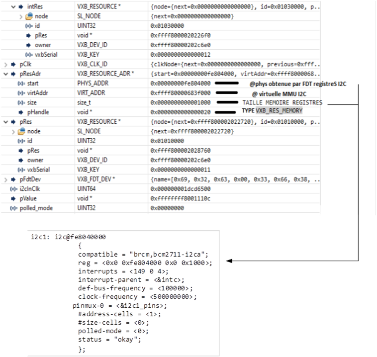
The VXB_RESOURCE_ADR structure used with the register
bank resources contains the physical start address of the register bank, its
virtual address and its size. The two resource types are VXB_RES_MEMORY and
VXB_RES_IO. VXB_RES_IO is only used for PCI on the ARM platform
Example: I2C driver
VXB_RESOURCE_ADR
* pResAdr = NULL; // memory resource structure for I/O
VXB_RESOURCE * pRes = NULL; // memory
resource structure for drivers
pRes = vxbResourceAlloc(pDev,
VXB_RES_MEMORY, 0); // allocate memory resources for the
structure VXB_RESOURCE memory resource information drivers
//pRes = vxbResourceAlloc(pDev, VXB_RES_IO, 0);
if (pRes == NULL)
{
I2C_DBG (I2C_DBG_ERR, "failed to allocate memory
resource");
goto errOut;
}
pResAdr = (VXB_RESOURCE_ADR *)pRes-> pRes; //the
member pRes of VXB_RESOURCE is an object of
type VXB_RESOURCE_ADR
if (pResAdr == NULL)
{
I2C_DBG (I2C_DBG_ERR, "failed to allocate memory
address resource\n");
goto errOut; }
9.4)
Management of physical resources
a) Management
of input and output pins
Some devices have inputs and outputs which are
declared by the pinmux-o variable in the device tree
as follows
i2c1: i2c@fe8040000
{
compatible = "brcm,bcm2711-i2ca";
reg = <0x0 0xfe804000 0x0 0x1000>;
interrupts = <149 0 4>;
interrupt-parent = <&intc>;
def-bus-frequency = <100000>;
clock-frequency = <500000000>;
pinmux-0 = <&i2c1_pins>;
#address-cells = <1>;
#size-cells = <0>;
polled-mode = <0>;
status = "okay";
};
The variable pinmux-o is
associated with the address i2c1_pins which is defined by :
i2c1_pins: i2c1Pins
{
pin-set = <2 4 1/*
gpio2 = sda, ALT0, PullUp */
3 4
1>; /* gpio3 = scl, ALT0, PullUp */

 };
In order to check
the conformity of its input/output pins the vxbPinMuxEnable(
) function is used.
vxbPinMuxEnable( ) - enable
the pinmux for the default state of a device
STATUS vxbPinMuxEnable
(
VXB_DEV_ID pDev
/* pinmux device handle */
)
This routine attempts to enable pinmux
for the default state of a specific device. Normally, a client device only
needs it to activate its default PINMUX configuration during boot time
initialization.
b) Clock
management
Some peripherals are connected to the internal clocks
of the circuit. The frequency of the clocks can be declared in the device tree
i2c1: i2c@fe8040000
{
compatible = "brcm,bcm2711-i2ca";
reg = <0x0 0xfe804000 0x0 0x1000>;
interrupts = <149 0 4>;
interrupt-parent = <&intc>;
def-bus-frequency = <100000>;
clock-frequency = <500000000>;
pinmux-0 = <&i2c1_pins>;
#address-cells = <1>;
#size-cells = <0>;
polled-mode = <0>;
status = "okay";
};
vxbClkEnableAll( ) enable
all clocks used by the device. This routine enables all clocks used by the
device.
The clock information is linked to the nodes in the
device tree.
if (vxbClkEnableAll (pDev)
== ERROR)
{
I2C_DBG (I2C_DBG_ERR, "failed to enable clocks");
return ERROR;
}
OK if all clocks are enabled, ERROR if all clocks
failed to be enabled.
vxbClkGet( ) -
returns the clock handler
VXB_CLK_ID vxbClkGet
(
VXB_DEV_ID pDev,
/* pointer to VxBus device */
const char * pClkName
/* name to lookup */
)
This routine uses two ways to find a clock handler:
first, it will try to find all clock registers in the clock list fdt that match the name of the clock. if this fails, it
will try to find in the clock domain platform the name of the clock. once
found, the clock handler is returned.
pClk = vxbClkGet (pDev, NULL);
if (pClk == NULL)
{
I2C_DBG (I2C_DBG_ERR, "failed to get clock ID.\n");
(void) vxbClkDisableAll
(pDev);
return ERROR;
}
vxbClkRateGet( ) - This
routine tries to get the clock rate
UINT64 vxbClkRateGet
(
VXB_CLK_ID pClk
/* clock handle */
)
i2cInClk
= vxbClkRateGet (pClk); //500 Mhz in dtb
if (i2cInClk == CLOCK_RATE_INVALID)
{
I2C_DBG (I2C_DBG_ERR, "failed to get clock rate. Using
default frequency\n");
i2cInClk = BCM2711_I2C_ICLK_FREQ;
}
c) Interruption
management
Memory resource allocation is also required with
resource type VXB_RES_IRQ
For interrupt
functions, the following functions are available, all of which use the VxBus interrupt resource manager:
VXB_RESOURCE * intRes ;
pDrvCtrl-> intRes = vxbResourceAlloc (pDev, VXB_RES_IRQ, 0);
if (pDrvCtrl-> intRes == NULL)
{
I2C_DBG (I2C_DBG_ERR, "vxbResourceAlloc
VXB_RES_IRQ fail.\n");
goto errOut;
}
The vxbIntConnect
function binds an ISR to a device interrupt resource.
STATUS vxbIntConnect
(
VXB_DEV_ID pDev, /* device descriptor */
VXB_RESOURCE * pRes, /* pointer to memory resource
structure */
VOIDFUNCPTR pIsr, /* pointer to ISR interrupt routine
*/
void * pArg /* ISR input parameter */
)
The vxbIntEnable function
enables an interrupt resource (at the PIC programmable interrupt controller).
STATUS vxbIntEnable
(
VXB_DEV_ID pDev, /* device
descriptor
VXB_RESOURCE * pRes /* pointer to memory resource
structure */
)
Disassociates an ISR from a device interrupt resource.
vxbIntDisconnect( )
Hides an interrupt resource (at PIC level).
vxbIntDisable( )
In a multicore system, routes an interrupt to a
specific core.
vxbIntReroute( )
pDrvCtrl-> intRes = vxbResourceAlloc (pDev, VXB_RES_IRQ, 0);
if (pDrvCtrl-> intRes ==
NULL)
{
I2C_DBG (I2C_DBG_ERR, "vxbResourceAlloc
VXB_RES_IRQ fail.\n");
goto errOut;
}
else
{
if
(OK != vxbIntConnect (pDev, pDrvCtrl-> intRes,(VOIDFUNCPTR) vxbBcm2711I2cIsr,pDev))
{
I2C_DBG (I2C_DBG_ERR, "vxbIntConnect
failed.\n");
goto errOut;
}
else
{
if (OK != vxbIntEnable (pDev, pDrvCtrl-> intRes))
{
I2C_DBG (I2C_DBG_ERR, "vxbIntEnable
fail.\n");
(void) vxbIntDisconnect
(pDev, pDrvCtrl-> intRes);
goto errOut;
}
printf("I2C Interrupt was
installed.\n");
}
}
Caution in ISR no access possible on
inputs and outputs
d) Interruptions
in the device tree
d.1)
concept
Interruptions are
service requests made by SOC devices
The SOC in its
environment is designed to process information in "real time". The
application is coupled to the outside world, through the frequent exchange of
messages and analogue signals at unscheduled times. In order to respond to
external requests, the SOC is obliged to change its state according to the
priorities of the current and requested operation.
Note:
Using interrupts allows the SOC to be relieved of certain repetitive tasks
(monitoring whether an external device is ready to place data on the data bus,
for example) that consume machine cycles. Indeed, with an efficient management
of interrupts, the SOC no longer needs to observe its environment (scanning)
permanently, thanks to the interrupt lines, the interfaces are able to stop the
running of the main program and to indicate that they require external
information to be taken into account.
|
Interrupts
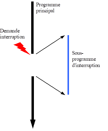
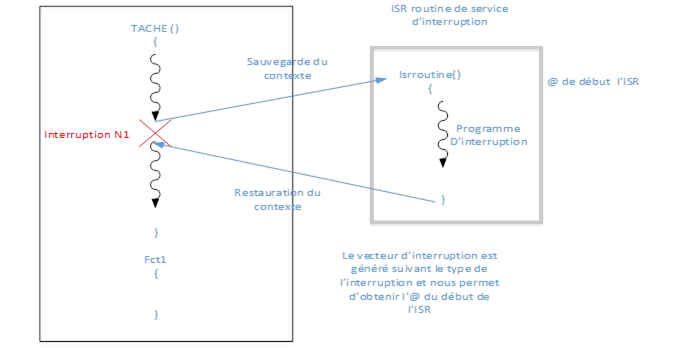
are events (usually external) or instructions that interrupt the current task
(after the current instruction has been executed), in order to run another
program (interrupt program). At the end of the latter, the task resumes
exactly where it was interrupted. There are therefore GPIO, I2C, SPI and
ETHERNET pins on the SOC dedicated to receiving interrupt requests. An
interrupt is usually asynchronous: it can occur at any time.
An interruption usually occurs for : ü report an event on a device ; ü request a dialogue between a peripheral and the CPU
core that runs the tasks.
|
|

d.2)
The key words of the device tree:
#interrupt-cells
This property
specifies the number of parameters it receives from an interrupt user device.
For this version of
the driver, it can be 1 or 3.
If
#interrupt-cells has a 1 parameter, then the parameter is the interrupt vector
number.
example:
interrupts = 34; this means that the interrupt number is 34.
If
#interrupt-cells has 3 parameters, the first parameter is the interrupt vector number,
the
second is the type of interrupt (0 for SPI, 1 for PPI),
the
last one corresponds to the interruption flags:
bit[3:0]
:
type of
interrupt trigger. 0x1 for rising edge trigger, 0x4 for active high level
trigger.
bit[15:8]:
interrupt CPU mask. indicate which CPU will handle this interrupt.
each bit represents one core, starting from core 0. If none bit is
set, core 0 will be chosen to handle this interrupt.
Note: for SPI, only one CPU target is allowed.
bit[23:16]:
interrupt priority.
Example:
interrupts = 34 0 4; this means that the interrupt vector is 34, the type is
SPI, the priority is 0, the link to the processor is 0, the high level trigger
is active.
max-int-lvl
This
property specifies the maximum number of interrupt requests supported by the
chip.
interrupt-controller
This
property specifies that this node is an interrupt controller of the SOC.
Example
intc: interrupt-controller@00a01000
{
compatible = "arm,gic";
interrupt-controller;
#interrupt-cells = <3>;
reg = <0x00a01000 0x1000>,
<0x00a00100 0x100>;
max-int-lvl = <160>;
};
explanation
of some abbreviations
CPC
- Cross Processor Call
IPI - Inter Processor Interrupt
GIC - General Interrupt Controller
SGI - Software Generated Interrupt
PPI - Private Peripheral Interrupt
SPI - Shared Peripheral Interrupt
gpio:
gpio@fe200000
{
compatible = "brcm,bcm2711-gpio";
gpio-controller;
#gpio-cells = <4>;
reg = <0x0 0xfe200000 0x0 0x00f4>;
interrupts = <145 0 1
146 0 1>;
interrupt-parent = <&intc>;
pinmux-0 = <&gpio_pins0>;
status = "okay";
};
d.3) Sources of
interruption
The raspberry PI4 (SOC BROADCOM 2711) has
a GIC-400 interrupt controller of the PPI and SPI type

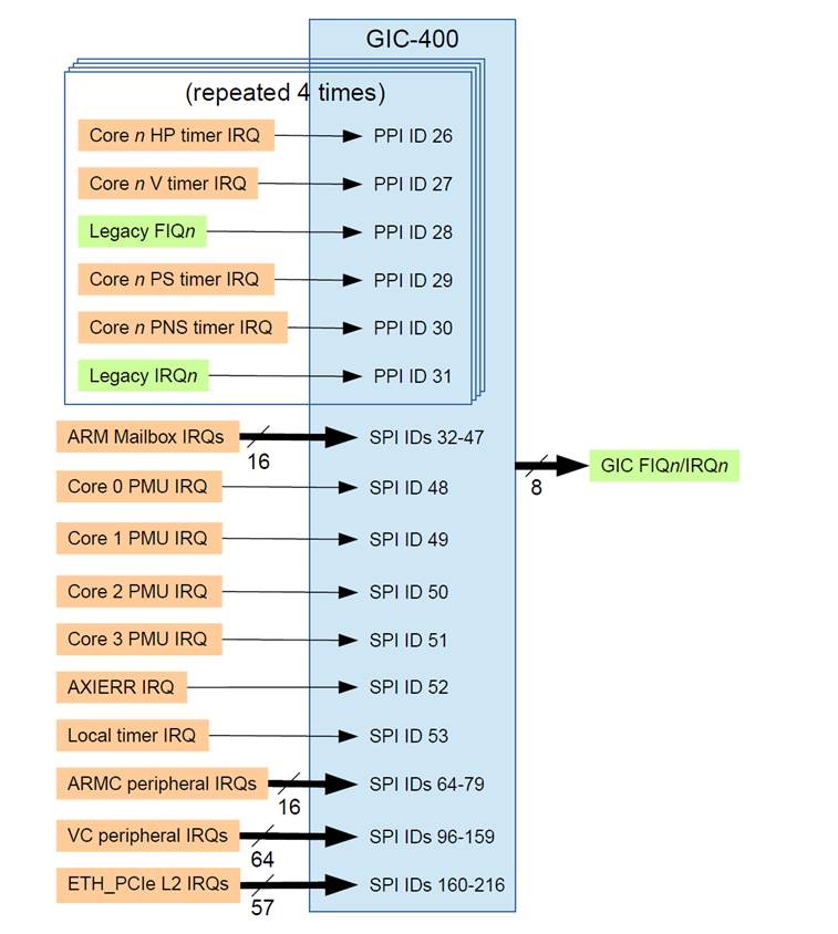
VC = videocore 64 IRQ NUMBER
The videocore has 64 interrupt lines (IRQ number)

Some
sources share the same IRQ number and therefore the same vector number (SPI I2C
and UART buses). It will therefore be necessary to search in the flags of the
peripheral interrupt registers for the source of the interrupt if several
peripherals share the same vector number.

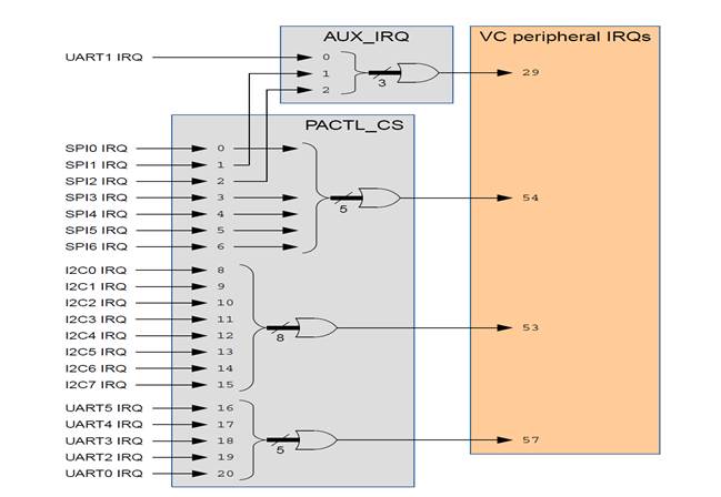
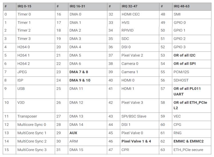
For the
I2C1 we will therefore have the vector 96+53=149
i2c1: i2c@fe8040000
{
compatible = "brcm,bcm2711-i2ca";
reg = <0x0 0xfe804000 0x0 0x1000>;
interrupts = <149 0 4>;
interrupt-parent = <&intc>;
def-bus-frequency = <100000>;
clock-frequency = <500000000>;
pinmux-0 = <&i2c1_pins>;
#address-cells = <1>;
#size-cells = <0>;
polled-mode = <0>;
status = "okay";
};
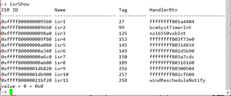
The isrshow command displays the implemented ISR routines with
the associated vector number (tag)
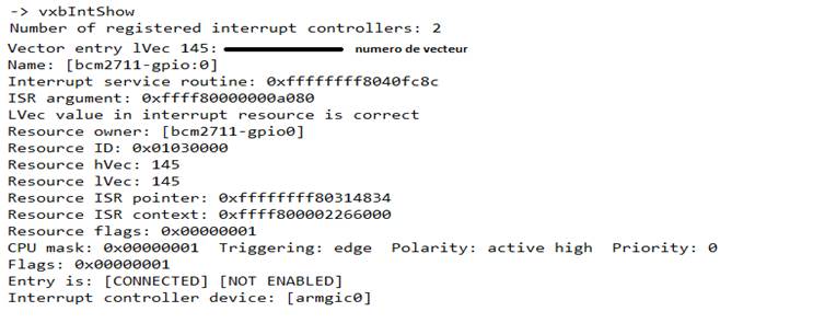
The vxbIntShow
command displays the interrupt settings for each device
Interrupts are
popular in order to avoid wasting processor resources but are not very popular
for the global determinism of the OS because a task can be pre-empted at any
time by an interrupt service routine. In a single-tasking context, it is
possible to ask for interrupts to be locked in a critical zone of a task in
order to keep this global determinism (intLock
function)
int intLock (void)
This routine disables interrupts. It can be called from the interrupt or task level. The intLock( ) routine returns an architecture-dependent lock key representing the interrupt level before the call; this key can be passed to intUnlock( ) to re-enable interrupts.
Calling a VxWorks system routine with locked interrupts may cause the interrupts to be re-enabled for an indeterminate period of time. If the called routine hangs or a higher priority task becomes READY, the interrupts will be re-enabled while another task is running or while the kernel is idle.
To prevent interrupts from being reactivated in the event that a called routine causes a higher priority task to become eligible for execution, the taskLock() primitive can be used to disable replanning. Note that if a task is blocked or suspended, the scheduler will always select the highest priority ready task to run (or become inactive), regardless of whether the task has locked the preemption via taskLock(), and so interrupts will be re-enabled.
The interrupt lock level is an attribute of a task, i.e. it is part of the task context.
Thus, if a task disables interrupts and then invokes a VxWorks system routine that causes the calling task to stall or prepare for a higher priority task, the interrupt lock level will be restored when the task execution is rescheduled later. For example, in the following code fragment, interrupts will be disabled after the return of the
taskDelay( ) :
lockKey = intLock ();
... (work with interrupts locked out)
taskDelay (sysClkRateGet() * 10); /* delay for 10 seconds */
... (work with interrupts locked out)
Finally, the above descriptions only
applies for tasks since ISRs are not permitted to block or suspend, and task
rescheduling only occurs when an ISR completes execution.
EXAMPLES
lockKey = intLock ();
... (work with interrupts locked out)
intUnlock (lockKey);
To lock out interrupts and task scheduling
as well (see WARNINGS above):
if (taskLock() == OK)
{
lockKey = intLock ();
... (critical section)
intUnlock (lockKey);
taskUnlock();
}
else
{
... (error message or recovery attempt)
}
intUnlock( )
void intUnlock
(
int lockKey /* lock-out key returned by preceding intLock() */
)
This
routine re-enables interrupts that were disabled by intLock(
). The lockKey parameter is an architecture-dependent
lock key returned by a previous intLock( ) call.
d.4) Interrupt handling in C
Memory resource allocation is also required with
resource type VXB_RES_IRQ
For interrupt
functions, the following functions are available, all of which use the VxBus interrupt resource manager:
VXB_RESOURCE * intRes ;
pDrvCtrl-> intRes = vxbResourceAlloc (pDev, VXB_RES_IRQ, 0);
if (pDrvCtrl-> intRes == NULL)
{
I2C_DBG (I2C_DBG_ERR, "vxbResourceAlloc
VXB_RES_IRQ fail.\n");
goto errOut;
}
The vxbIntConnect
function binds an ISR to a device interrupt resource.
STATUS vxbIntConnect
(
VXB_DEV_ID pDev, /* device descriptor */
VXB_RESOURCE * pRes, /* pointer to memory resource
structure */
VOIDFUNCPTR pIsr, /* pointer to ISR interrupt routine
*/
void * pArg /* ISR input parameter */
)
The vxbIntEnable function
enables an interrupt resource (at the PIC programmable interrupt controller).
STATUS vxbIntEnable
(
VXB_DEV_ID pDev, /* device
descriptor
VXB_RESOURCE
* pRes /* pointer to memory resource structure */
)
Disassociates an ISR from a device interrupt resource.
vxbIntDisconnect( )
Hides an interrupt resource (at PIC level).
vxbIntDisable( )
In a multicore system, routes an interrupt to a specific
core.
vxbIntReroute( )
pDrvCtrl-> intRes = vxbResourceAlloc (pDev, VXB_RES_IRQ, 0);
if (pDrvCtrl-> intRes ==
NULL)
{
I2C_DBG (I2C_DBG_ERR, "vxbResourceAlloc
VXB_RES_IRQ fail.\n");
goto errOut;
}
else
{
if
(OK != vxbIntConnect (pDev, pDrvCtrl-> intRes,(VOIDFUNCPTR) vxbBcm2711I2cIsr,pDev))
{
I2C_DBG (I2C_DBG_ERR, "vxbIntConnect
failed.\n");
goto errOut;
}
else
{
if (OK != vxbIntEnable (pDev, pDrvCtrl-> intRes))
{
I2C_DBG (I2C_DBG_ERR, "vxbIntEnable
fail.\n");
(void) vxbIntDisconnect
(pDev, pDrvCtrl-> intRes);
goto errOut;
}
printf("I2C Interrupt was
installed.\n");
}
}
Attention in ISR no access possible on the
inputs and outputs
Accessibility of
methods in the pilot
We add
a new structure in the device descriptor that will allow us to point to the
different functions of the driver
typedef
struct bcm2711_GP0Ctl_drv_ctrl
{
DEV_HDR
devHdr; //system header contains the system name the driver
number @ system descriptor is also @system header
VXB_DEV_ID pDev;
void * baseAddr; //pRegBase
void * handle;
VXB_RESOURCE * gp0ctlRegRes;
VXB_RESOURCE * pinRegRes;
UINT32 clkFrequency;
struct vxbGp0ctlFunctionality pGp0ctlFunc;
} BCM2711_GP0CTL_DRVCTRL;
struct
vxbGp0ctlFunctionality
{
BOOL allocated; /*
flag used to denote timer allocation */
STATUS (*GP0Ctlinit)
(
void * pCookie,
UINT32 div
);
STATUS (*GP0CtlDisable)
(
void * pCookie
);
};
In the
attachment function we will make the link between methods reachable by the user
and declared in the previous structure and the methods of the driver
LOCAL STATUS vxbBcm2711GP0CtlAttach
(
VXB_DEV_ID pDev
)
{
BCM2711_GP0CTL_DRVCTRL * pDrvCtrl;
struct vxbGp0ctlFunctionality * pTFunc;
pTFunc = &pDrvCtrl->
pGp0ctlFunc;
pTFunc-> GP0Ctlinit
= vxbBcm2711GP0CtlInit;
pTFunc-> GP0CtlDisable=vxbBcm2711GP0CtlDisable;
Special case of the GPIO controller
The two vxbFdtBcm2711Gpio libraries
associated with the generic vxbGpioLib library allow
the implementation of interrupts on the GPIO without explicit declaration of
the GPIO device descriptor. The functions are as follows:
The vxbGpioIntConnect function binds an ISR to a
device interrupt resource.
STATUS vxbGpioIntConnect
(
UINT32 id, /* GPIO ID */
VOIDFUNCPTR pIsr, /* ISR */
void * pArg /* parameter */
)
The vxbGpioIntConfig function is used to configure
the interrupt
STATUS vxbGpioIntConfig
(
UINT32 id, /* GPIO ID */
INTR_TRIGER trig, /* trigger mode */
INTR_POLARITY pol /* polarity */
)
This routine sets the interrupt trigger mode and its polarity.
The trig argument specifies the trigger mode. This argument could be any of the
following values: INTR_TRIGGER_CONFORM :0 - does not change the trigger mode of
the device tree
. INTR_TRIGGER_EDGE:1 - edge-triggered interrupt.
INTR_TRIGGER_LEVEL :2 - level triggered interrupt.
The pol argument specifies an interrupt polarity. This argument could be any of
the following values: INTR_POLARITY_CONFORM :0 - does not change the device
tree interrupt
polarity. INTR_POLARITY_HIGH :1 - logic level high/rising edge.
INTR_POLARITY_LOW :2 - logical low level/downward edge.
The vxbGpioIntEnable function enables an
interrupt resource
STATUS vxbGpioIntEnable
(
UINT32 id, /* GPIO ID */
VOIDFUNCPTR pIsr, /* ISR */
void * pArg /* parameter */
)
10) Association of a device with an input-output
system
we will
associate a device via a file descriptor. Calling the device drivers will be
done through the :
- open/creat/close/remove
- read/write/ioctl
- a device will be
associated with one and only one driver. The driver handles requests to the
device through its xxopen xxwrite
methods .....
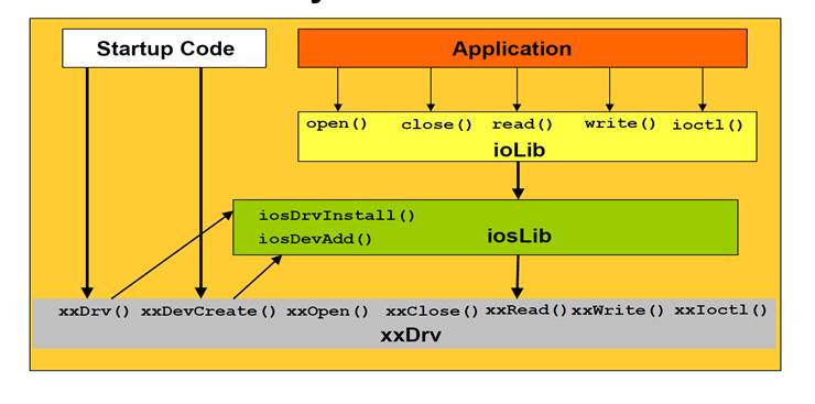
The use
of a device as an I/O device has the following purpose
- hide
material constraints
-
decouple the application from the material
-
protect/share access
The
Principles adopted are :
- a
device is seen as a file
- The
use of the input/output system (IOS)
- standardised IOS primitives
call by device
open/creat/close/remove
read/write/ioctl
- a
device is associated with one and only one driver
- the driver handles requests on the device
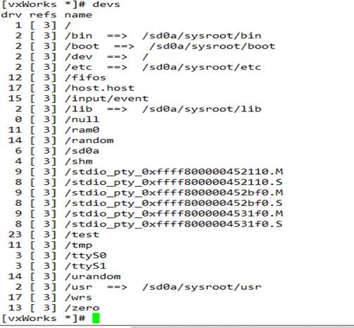
The devs
command provides a list of device descriptors
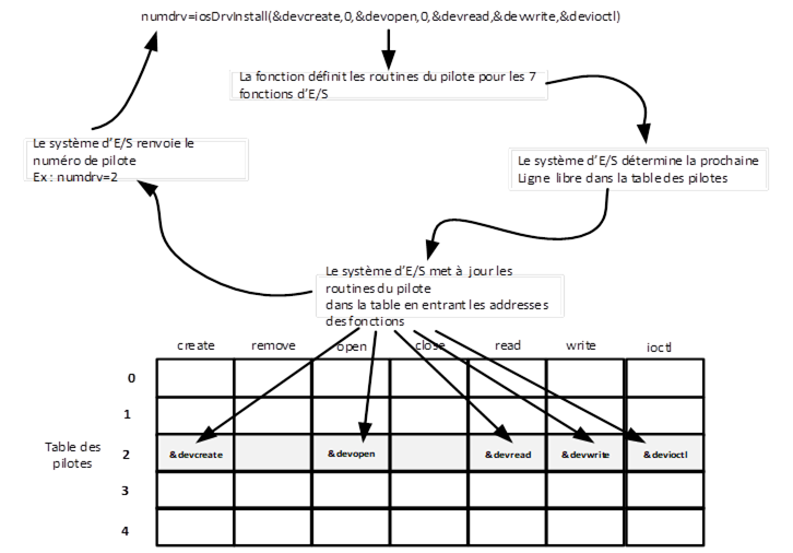
Installation of an I/O
driver
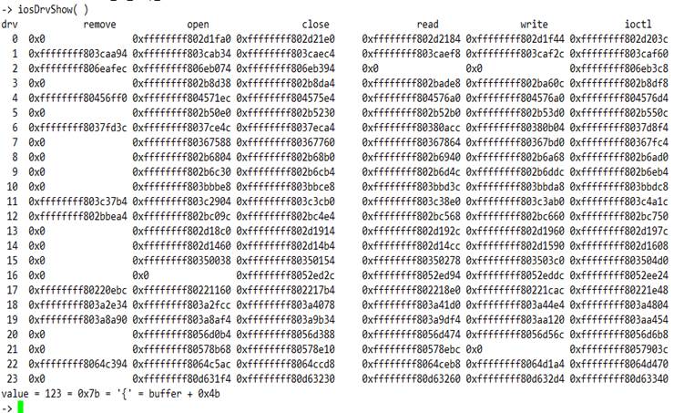
iosDrvInstall( ) - installs
a kernel I/O driver
This routine must be called once by each
I/O driver.
It connects the various I/O service calls
to the driver service routines and assigns a number to the driver by adding the
driver to the driver table. It returns the driver number
int iosDrvInstall
(
DRV_CREATE_PTR pCreate, /* unused */
DRV_REMOVE_PTR pRemove, /* pointer to driver remove
function */
DRV_OPEN_PTR pOpen, /* pointer to driver open
function */
DRV_CLOSE_PTR
pClose, /* pointer to driver close function */
DRV_READ_PTR pRead, /* pointer to driver read
function */
DRV_WRITE_PTR pWrite, /* pointer to driver write
function */
DRV_IOCTL_PTR pIoctl /* pointer to driver ioctl function */
)
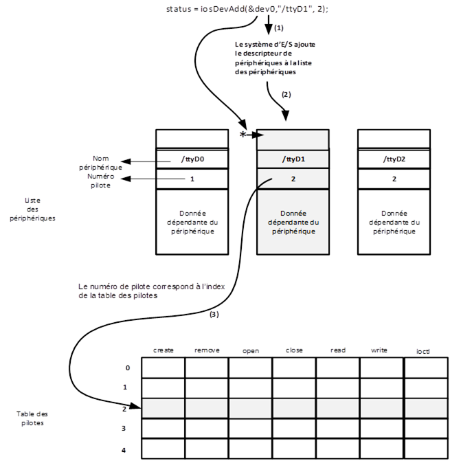
Adding
the device descriptor to the device list
Character devices
are dynamically added to the system I/O list by calling the internal I/O
routine iosDevAdd()
STATUS iosDevAdd
(
DEV_HDR
* pDevHdr, /* device descriptor */
const
char * name, /* name of the output input system */
int drvnum /* driver number*/
/* returned by iosDrvInstall() */
)
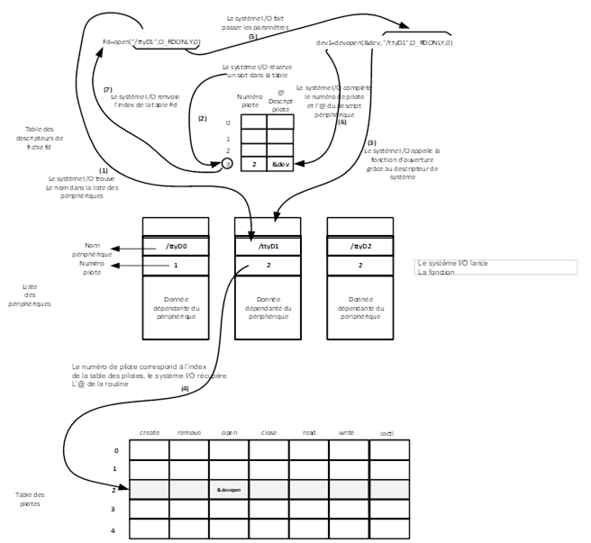
10.3) opening an input-output device
The
mechanism for opening a device is described in 7 steps
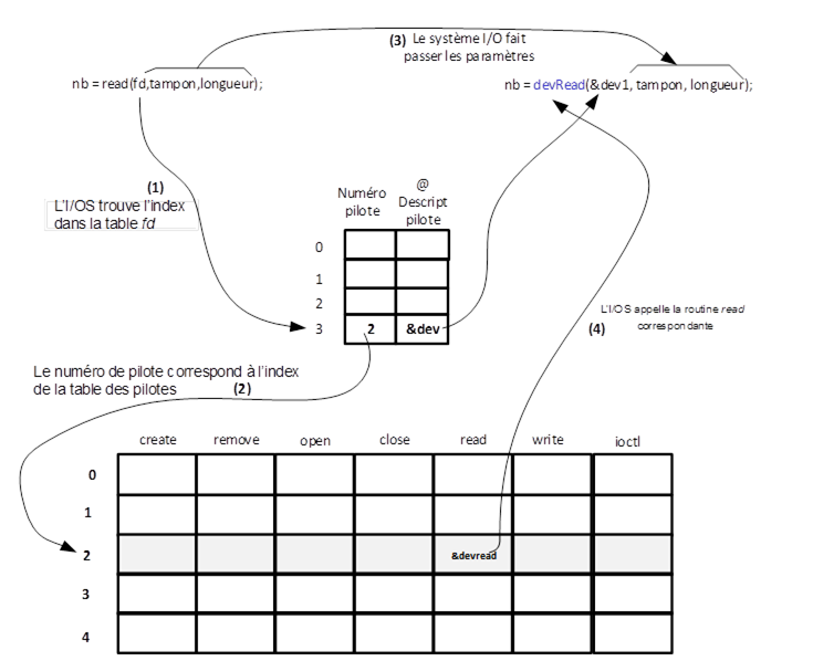
10.4) reading an input-output device
The
mechanism for reading a device is described in 4 steps
Uninstalling and
removing a device
Int ret = iosDrvRemove (int drvNumber,int protOpen)
ret= FALSE: driver
not uninstalled if a device is open
ret=TRUE: an open
device is closed and implicitly destroyed, the driven one is uninstalled
withdrawal
status = iosDevDelete( DEV_HDR * pDevHdr );
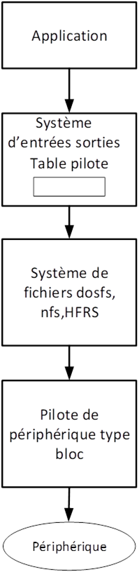
Block device drivers
interact with a file system
11)Creating a stand-alone environment on SDCARD
It is interesting
in an embedded environment to have a card that is completely autonomous without
a PC nearby. A board capable of launching applications in standalone mode.
Several methods exist under Vxworks when creating the
kernel
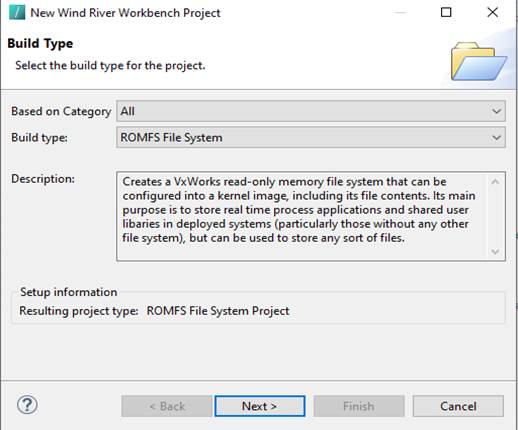
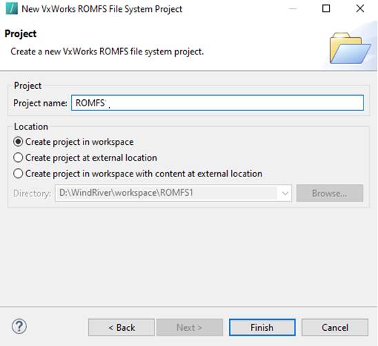
A ROMFS file system project offers the
possibility of grouping applications
and VxWorks files with the operating
system without the need for a local disk or a network connection to a remote
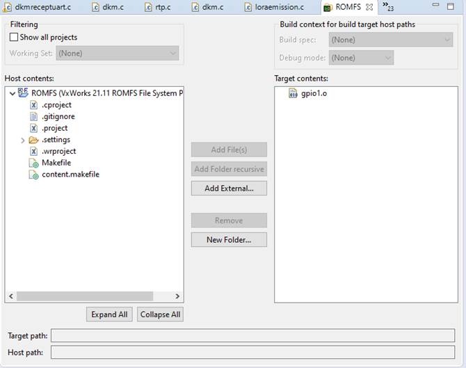
disk. When VxWorks is configured with the ROMFS file system, files of any type
can be included in the operating system image by adding to a ROMFS directory on
the host system. The build produces a single system image that includes both
VxWorks and the files in the ROMFS file system directory.
When VxWorks is booted with this image,
the ROMFS file system and the files it contains are loaded with the kernel. In
addition, RTP applications can be coupled with an automated boot function so
that they run automatically at boot time. A ROMFS file system thus offers the
possibility of creating fully autonomous systems.



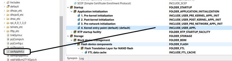
11.3) Launching a DKM at start-up
Have the INCLUDE_USER_APPL component
checked in the VIP
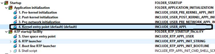
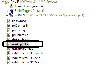
Adds a call to the entry point function of
the myAppStartup application in the usrAppInit.c file
/******************************************************************************
*
* usrAppInit - initialize the users application
*/
void usrAppInit (void)
{
#ifdefUSER_APPL_INIT
USER_APPL_INIT;
/* for backwards compatibility */
#endif
/* TODO: add application
specific code here */
myAppStartup();
}
You can use the VxWorks application
startup function in conjunction with the usrRtpAppInit(
) initialization function to start applications automatically when VxWorks
starts.
To use this method, VxWorks must be
configured with the INCLUDE_RTP_APPL_USER component, which includes the file in
your project automatically
.
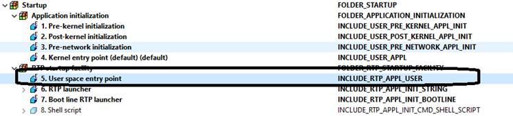
For each application you want to start,
add an rtpSpawn( ) call and the associated code to
the usrRtpAppInit( ) function stub.
The following example starts an
application called myVxApp with three arguments:
void usrRtpAppInit (void)
{
char * vxeName = "c:/tmp/myVxApp.vxe";
char * argv[5];
RTP_ID rtpId = NULL;
/* set the
application's arguments */
argv[0] = vxeName;
argv[1] =
"first";
argv[2] =
"second";
argv[3] =
"third";
argv[4] =
NULL;
/* Spawn the RTP.
No environment variables are passed */
if ((rtpId = rtpSpawn (vxeName, argv, NULL, 220,
0x10000, 0, 0)) == NULL)
{
printErr
("Impossible to start myVxApp application (errno = %#x)", errno);
}
}
In the example above, the myVxApp.vxe
application executable is stored on the host system in c:\tmp.
You can also store the executable in ROMFS on the
target system where the assignment statement identifies the executable as
follows:
char * vxeName = "/romfs/myVxApp.vxe";
There are other methods to start an RTP
process when the card is booted:
- Boot lines can be included in
the kernel
- A script file can be created
12) GPIO programming: General purpose input/output pins
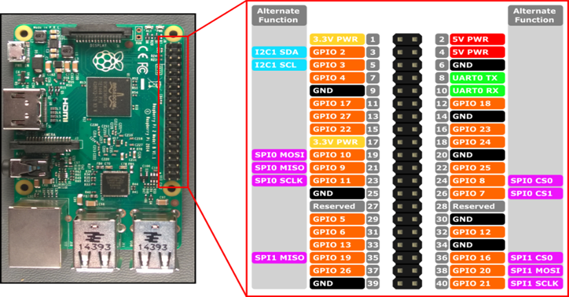
The Raspberry PI4 GPIO input/output pins
range from GPIO0 to GPIO27 (GPIO0 and GPIO1 are reserved). Some pins are not
usable because they are shared with other devices (ALT0 to ALT5 alternate
functions).

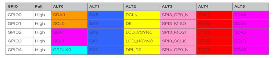
When configuring the kernel and the device
tree, you can specify for each GPIO pin which alternate function is to be used.
/*
* Function selection:
*
* 0 = GPIO pin is an input
* 1 = GPIO pin is an output
* 4 = GPIO pin takes alternate function 0
* 5 = GPIO pin takes alternate function 1
* 6 = GPIO pin takes alternate function 2
* 7 = GPIO pin takes alternate function 3
* 3 = GPIO pin takes alternate function 4
* 2 = GPIO pin takes alternate function 5
*
* Pin Mode selection:
*
* 0 = float
* 1 = pull-up
* 2 = pull-down
*
*/
gpio_pins0:
gpioPins0
{
pin-set = <17 0 1/*
gpio17 = input, pull up */
27 1 0>; /*
gpio27 = output*/
};
gpio:
gpio@fe200000
{
compatible = "brcm,bcm2711-gpio";
gpio-controller;
#gpio-cells = <4>;
reg = <0x0 0xfe200000 0x0 0x00f4>;
interrupts = <145 0 1
146 0 1>;
interrupt-parent = <&intc>;
pinmux-0 = <&gpio_pins0>;
status = "okay";
};
Spindle programming in C language
#include "../gpioLib/gpioLib.h"
Assigning
an input/output pin
void pinMode(int pinnumber, int type)
int
type: IN or OUT
void vxbGpioSetDir(int numberpins, int
type);
int
type : IN=0 or OUT=1
Writing
a logic level to an I/O pin
void gpiowrite(int numberpins, int
value)
int
value: HIGH or LOW
Reading
a logic level on an I/O pin
int gpioread(int numberpins, int
value)
return
value 0 or 1 depending on the logic level of the pin
Release
of an input-output pin
void gpiofree(int numerobroch)
The pin
number corresponds to the number following the GPIO
Example
GPIO17 gives us pinnumber=17
13) Communication and synchronization
between tasks and processes
The
inter-task and inter-process functions of VxWorks provide mechanisms for
synchronizing the activity of different tasks
and
communication between them. For inter-process and kernel-process communication,
VxWorks semaphores and message queues, pipes and events (as well as POSIX
semaphores and events) can be created as public objects to provide inter-task
communication across memory boundaries (between the kernel and processes, and
between different processes).
Shared
data structures (dkm rtp)
Provide
a means for tasks running in the same memory space (kernel or RTP) to
communicate by accessing data structures.
Interrupt
locking (dkm core only)
Provide
a means of disabling interrupts, and thus preventing preemption by ISRs.
Interrupt locking is not a general purpose mechanism, and should only be used
in a very limited way.
Locking
of tasks (dkm core only)
Provide
a way to disable preemption by other tasks. Task locking is a mechanism
It is a
general danger and should only be used in a very limited way.
The
Semaphores (dkm rtp)
Provide
the primary means of task synchronization and mutual exclusion. The general
purpose and specialized variants are
available.
Semaphores can be created as public objects, which allows their use in
inter-process communication.
Kernel
queue messages (dkm)
Provide
a top-level mechanism for direct communication of messages between tasks.
Message
queues can be created as public objects, allowing them to be used in
inter-process communication
The
tubes (dkm, rtp)
Provide
an alternative messaging interface to the message queue function. The tubes
operate via the I/O system.
Events
(dkm)
Provide
a means of communication and synchronization between tasks and other tasks,
interrupt service routines (ISR) and
tasks,
semaphores and tasks, and message and task queues.
|
Name |
communication |
synchronization |
access |
|
Shared data structures |
x |
x |
DKM RTP |
|
Interrupting interruptions |
|
x |
DKM |
|
Spot Locking |
|
x |
DKM |
|
Semaphores |
|
x |
DKM RTP |
|
Queue messages |
x |
|
DKM |
|
The tubes |
x |
|
DKM RTP |
|
The events |
|
x |
DKM |
taskLock( )
NAME
taskLock( ) - disable task rescheduling
STATUS taskLock (void)
DESCRIPTION
This
routine disables task context switching. The task that calls this routine will
be the only one
task
that is allowed to run, unless the task explicitly abandons the CPU by making
itself
is
no longer ready. Typically, this call is associated with taskUnlock(
); together they enclose a
critical
section of the code. These preemption locks are implemented with a count
variable
which
allows nested preemption locks. The preemption will not be unlocked until taskUnlock()has been called as many times as taskLock().
This
routine does not lock interrupts; use intLock( ) to
lock interrupts.
A taskLock() is preferable to intLock()
as a means of mutual exclusion, as an interrupt
locks
add interrupt latency to the system
A semTake() is preferable to taskLock()
as a means of mutual exclusion
The taskLock( ) routine
cannot be called from the interrupt service routines.
14) THE I2C BUS
SUMMARY SHEET
Presentation:
I2C
is a serial bus for transmitting information asynchronously between various
circuits connected to the bus.
The
protocol of the link is of the MASTER/ESCLAVE type. Each circuit is recognised by its address and can either transmit or
receive information.
Two
wires, SDA (Serial DAta) and SCL (Serial CLock), carry the information between the different
circuits. SDA and SCL are bidirectional lines, connected to plus VCC via two
pull-up resistors.
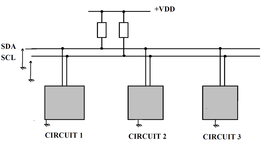
When
the bus is free, i.e. when there is no data transfer, both lines are in the
high state.
For
the transfer of a bit to be valid the data on the SDA line must be stable while
the clock is high on SCL.
The
SDA value can only change when SCL is in the low state.
A
message starts with a START condition (S) and ends with a STOP condition (P).
START
condition: Change from high to low state of SDA while SCL is in high state.
STOP
condition: Change from low to high state of SDA while SCL is in high state.
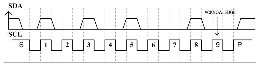
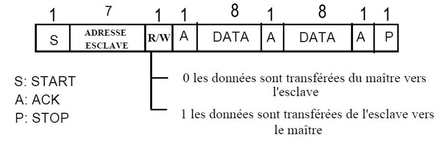
Data
transfer on the bus: Data is transferred in 8-bit packets (1 byte). Each byte
must be followed by an acknowledge bit.
In
the first byte transferred the first seven bits represent the slave address and
the eighth bit is the read/write bit
On
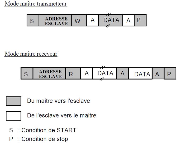
the I2C bus, there will always be one and only one master controller and it is
this one that synchronises the exchanges by providing
the clock signals on SCL
Software
aspect: use of the I2C under Vxworks 7
We will use the device driver associated with the input/output. The file
descriptor that allows the exchange is called /I2C/0 (see the devs command)
Opening :
In the kernel domain (DKM) We will open this driver
fd = open("/I2C/0", 3, 555))
fd =-1 in case of problem otherwise fd=the value
of the file descriptor
I2C bus configuration
we
use the IOCTL function with a function code associated with the command
ioctl(int fd, int numerocode, type parameter) ;
|
numeroCode |
Type of parameter |
description |
|
510 |
int |
Programming of the bus speed in bits/s |
|
511 |
UINT8 |
Programming @ of the slave |
|
512 |
UINT8 |
Number of clock cycles to wait after the falling
edge of SCL before writing the next data bit |
|
513 |
UINT8 |
Number of clock cycles to wait after the rising edge
of SCL before reading the next data bit |
Example:
ioctl(fd,510,100000);
//prog freq
100000hz
Read
or write on the I2C bus
Write
command with transmission of the previously configured slave address
write(int fd, UINT8
command[] ,int commandLength)
int fd: file descriptor
UINT8
command[]: array of bytes to send
int commandLength: number of bytes to send
if
commandLength=0 the slave address is sent
reading
order
read(int fd, UINT8
buffer[] ,int Lengthbuffer)
int fd: file descriptor
UINT8
buffer[]: byte array where each read byte is stored
int Lengthbuffer: number of bytes to read
example
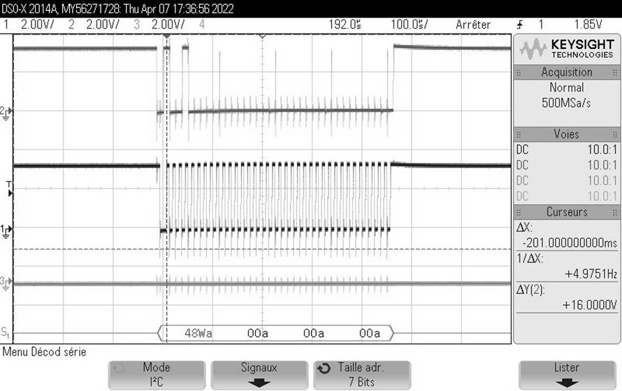
writing (slave address 0x48) :
Command[0]=0x00
;
Command[1]=0x00
;
Command[2]=0x00
;
commandLength=3;
if (write(fd,command, commandLength))
{
return false;
Read
command (slave address 0x48) :
replylen = 1 ;
replybuffer[1] ;
if (read(fd, replybuffer,
replylen)<0) {
return false;
}
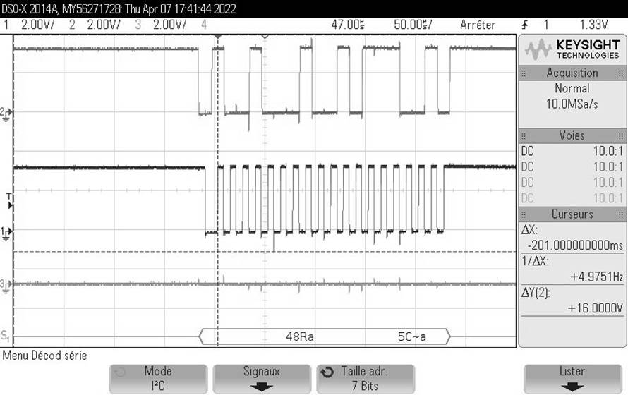
replybuffer[0]=0x5C
15)
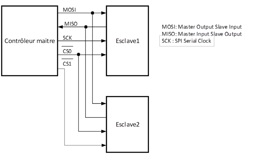
THE SPI BUS in full duplex mode: SUMMARY
The
SPI (Serial Peripheral Interface) bus is a serial bus developed by Motorola. It
consists of a master controller and one or more slaves selected by a chip
select CS line.
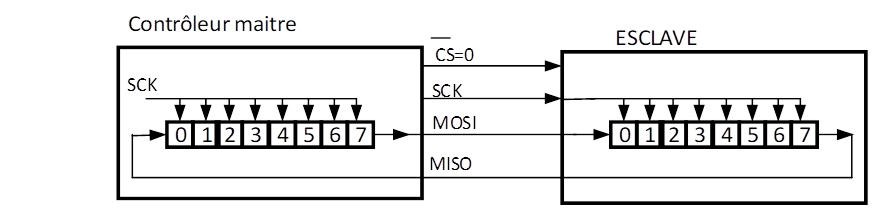
Two
shift registers are cascaded together so that when the master controller sends
an SCK-synchronised data, the slave sends a SCK-synchronised response at the same time.
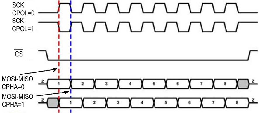
There
are four modes of transmission:
CPOL=0
Clock at rest is in low state
CPOL=1
Clock at rest is in high state
CPHA=0
the bit is taken into account on a rising edge of the clock
CPHA=1
the bit is taken into account on a falling edge of the clock
Software
aspect: use of the SPI under Vxworks 7
We will use the device driver associated with the input/output. The file
descriptor that allows the exchange is called /SPI/0 (see the devs command)
Opening :
In the kernel domain (DKM) We will open this driver
fd = open("/SPI/0", 3, 555))
fd =-1 in case of problem otherwise fd=the value
of the file descriptor
SPI bus configuration
we
use a configuration mode array of 11 unsigned long integers as the last
parameter of the write function to configure the SPI bus
UINT32 mode[11]={0x00}; // array configuration mode
Byte 4 box 3 of the table is used to program the bus
speed in bits/s
mode[3]=50000; //50000hz
Byte 5 box 4 allows the bus to be configured for each
bit. Constants are predefined and the
association of these by or or and logic allows the
configuration of the SPI bus
#define
SPI_CSPOL_L 0xFB
( bit 2 to logical
0)
#define
SPI_CSPOL_H 0x04 (bit 2 to logical 1)
#define
SPI_CLK_POLH
0x02 (bit 1 to
logical 1)
#define
SPI_CLK_POLL
0xFD (logical bit 1
to 0)
#define
SPI_CLK_PHASEM 0xFE (bit 0 to
logical 0)
#define
SPI_CLK_PHASES 0x01
(logical bit
0 to 1)
#define
FULL_DUPLEX 0x20 (bit 1 to logical 1)
#define
FULL_NODUPLEX 0xDF
(bit 5 to logical 0)
#define
INTERRUPT
0xBF
(bit 6 to logical 0)
#define
POLLING
0x40
(bit 6 to logical 1)
SPI_CSPOL_H :CS=1 at rest
SPI_CSPOL_L :CS=0 at rest
SPI_CLK_CPOL_H :CPOL=1 at rest
SPI_CLK_CPOL_L :CPOL=0 at rest
SPI_CLK_PHASEM :CPHA=0
SPI_CLK_PHASES :CPHA=1
FULL_DUPLEX:
full duplex transmission mode
FULL_NODUPLEX:
non-full duplex transmission mode
INTERRUPT:
Interruption management
POLLING:
management by polling
Example
of use
mode[4]=mode[4]|SPI_CSPOL_H|SPI_CLK_POLH
| FULL_DUPLEX;
mode[4]=mode[4]& SPI_CLK_PHASEM;
mode[4]=mode[4]&INTERRUPT;
mode[5] =0 // CS0 pin active on PI4
mode[5]
=1 // CS1 pin active on PI4
read
and write order on SPI:
write(int fd , uint8_t buffer[], int lenghtbuffer, uint8_t bufrec[],int lenghtbufrec, UINT32 mode[11])
int fd:
file descriptor
uint8_t
buffer[]:
byte array to send
int
lenghtbuffer:
number of bytes to send
UINT8
bufrec[]:
byte array where each byte read is housed
int int lenghtbufrec:
number of bytes to read
UINT32 mode[11] : configuration mode
table
Writing to the SPI bus
char rx[2], tx[2];
tx[0]=(0x89);
tx[1]=82;
if ((ret=write(spid,tx,
2,rx,0,mode))<0) {
printf("impossible writing");}
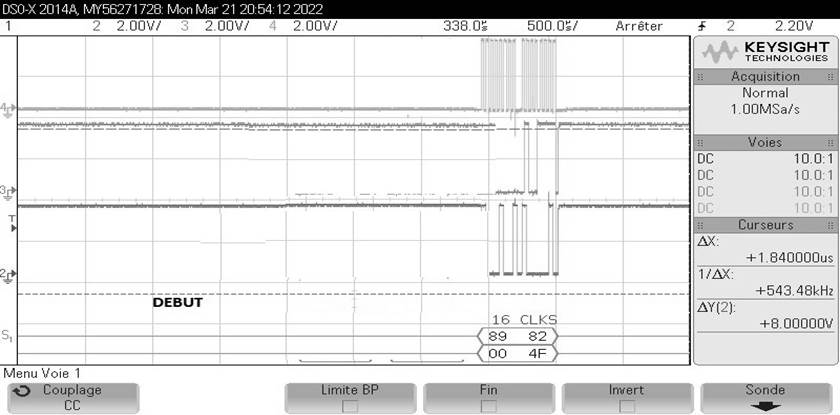
Reading on the SPI bus
tx[0]=0x3C;
tx[1]=0x00;
rx[0]=0x00;
rx[1]=0x00;
if ((ret=write(spid,tx,2,rx,2,mode))<0) {
printf("impossible
writing");}
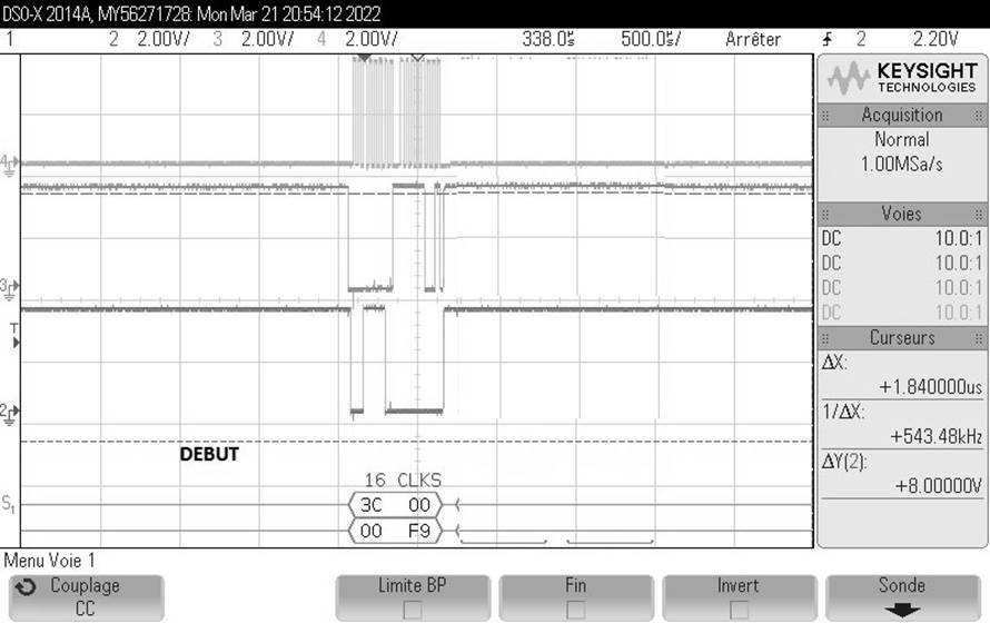
Rx[0]=0x00
;
Rx[1]=0xF9
;
16) The PWM
controller
The
Raspberry PI4 has a two channel PWM controller (channel1, channel2 see below).
To have additional channels you will need to add another controller on the SPI
or I2C bus
The
programming in the core area remains as follows:
Opening :
In the kernel domain (DKM) We will open this driver
fd = open("/PWM/0", 3, 555))
fd =-1 in case of problem otherwise fd=the value
of the file descriptor
PWM configuration
we
use an array of 4 unsigned long integers as the last parameter of the write
function to configure the PWM controller
// configuration mode table
UINT32 buffer[4];
buffer[0]=50;// frequency channel1 hz
buffer[1]=50;// frequency channel2 hz
buffer[2]=6;// ratio channel1 %.
buffer[3]=2;// ratio channel2 %.
if (write(fd,buffer, 4)) {
close(fd);
return false;
}
17) Vxworks
commands
The
usual commands
C
to return to the shell code interpreter
cmd
to return to the command shell of the code interpreter
ifconfig
-a
Network config
info
ls
lists the names of the files in the
ls
-l
lists the file names in the directory in more detail
i
Info on tasks performed
pwd
Info on our directory and tree structure
td < spotname>
kill a spot
td
0x________
kill a spot by its TID
ti < spotname>
info about a task
h
displays the last commands typed
printLogo
displays the Vxworks logo
ld < modulename>
load a module
unld <modulename> to unload a module
cd /
return to root
devs
lists the managed devices
cp
copy a file from one directory to another (same as Linux)
mkdir <directory name> create a
directory
netstat
-a
Information on open ports
ping <IP
address>.
ping an IP address
version
to know the version of Vxworks
ipd
list
list of daemon servers
ipd kill
<name>
list of daemon servers
ipd
start<name>
list of daemon servers
sd
SHared data visualize the shared
data
areas
esc K
- go back in history
esc J
- go forward in history
rtp task
To view the current RTP tasks
task stop
<name>
stop the RTP task in bear
task continue
<name>
restart the current RTP task
Non-standard
functions or commands
moduleShow
see the list of loaded modules
lkup < name>
Gives the table of symbols (functions) and variables loaded by the kernel
semShow
Gives the list of semaphores
iosDrvShow
Gives a list of the loaded device drivers and their numbers
vxbDrvShow
Gives the list of loaded device drivers and their classes
vxbDevShow
Gives the list of loaded device drivers and their classes
vxbDevShowPaths
Gives the list of device drivers and their paths in the device tree
iosFdShow
Gives the list of device descriptors
vxFdtDtbDump
List the device tree DTB
vxbIntShow
Gives the list of managed interrupts the vector number
isrShow
Gives the list of ISRs and associated vector numbers
vxbPinMuxShow lists the pinmux controllers
vxbGpioShow
lists the hogged GPIO pins
iosDevShow
lists the inputs and outputs
rtpShow
lists the loaded real time RTP processes
adrSpaceShow memory info
sp
Spawn a task
rtpSp* .vxe
checkStack()
sdShow
show
bootline